
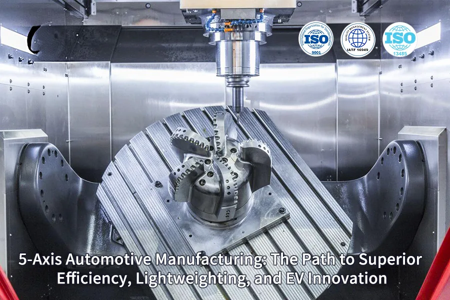
A single setup on a five-axis centre: the angled faces, ports and pockets arrive in one coordinate system instead of three fixtures.
Lightweighting and electrification pull in the same direction on the drawing and in opposite directions on the shop floor. Structural parts have to shed mass while taking the same loads, and an EV adds a battery enclosure that has to seal across two metres of aluminium. Both mean fewer parts, more complexity per part, and tolerances that a three-axis sequence struggles to hold because every re-clamp adds error to the stack.
Five-axis machining resolves that by removing the re-clamps. Complex geometry is cut from one datum, in one operation, on a part that is only positioned once — which is what makes integrated, topologically optimised, thin-walled automotive components manufacturable at all.
What this guide covers
- The economics: one setup replaces several, so cumulative fixturing error and stock waste leave the process.
- The hard problems: distortion on large trays, chip evacuation in 5:1 bores, and machine geometry that has to be mapped and compensated.
- The numbers: 1.2 mm walls held inside about 0.05–0.1 mm, sealing faces at 0.1 mm flatness over 2 m, bores at 0.008 mm cylindricity.
- The checks: in-process probing, thermal stabilisation, laser interferometer and ballbar calibration, and part-level traceability.
Why 5-Axis Suits Lightweight and Electric Vehicles
The automotive parts that gained the most from five-axis work are the ones that were previously made as assemblies. A chassis node, a motor housing with an internal water jacket, a battery tray with cooling channels and threaded inserts: each is a single part whose features sit on many planes, and each becomes simpler, lighter and stiffer when it is machined as one piece rather than bolted together from several.
On a three-axis machine that usually means multiple setups. Each re-clamp introduces a new datum with its own small error, and those errors add; features that cannot be reached at all from a given orientation have to be moved to another machine, or designed out. Five-axis removes both constraints. The cutting tool is oriented to the surface rather than the workpiece being turned toward the tool, so undercut and angled features are reachable without a fixture that fights the geometry.
Three outcomes follow directly: fewer operations, less material left as chips, and a part that can be machined closer to its final topology-optimised shape — which is where the mass saving actually lives.
One Setup, One Datum: What That Changes
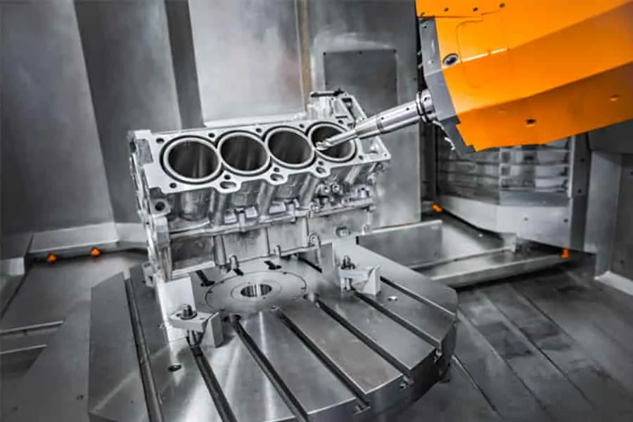
A casting with every critical face, bore and port machined from one workpiece coordinate system — no re-clamping between operations.
The mechanism is not complicated, and it is where most of the gain sits. Establish one workpiece coordinate system on the casting, and every toolpath is calculated against that single datum. Machining then reaches every significant surface without the part moving, which eliminates both the misalignment between setups and the error that accumulates each time it does move.
Two practices make the single setup reliable in production:
- Dynamic tool orientation with collision checking. CAM software positions the tool at an optimum angle for each feature and rotates it through the cut instead of reaching in from a fixed direction. Before any metal is cut, the whole program runs against a virtual twin of the machine, fixture and part so interference is found in software rather than on the machine.
- In-process probing on the same datum. Routine probing of datum and bore positions after roughing measures what the casting actually did, and the offset is applied before finishing. On a well-controlled process that keeps final positional tolerances to around ±0.025 mm on a part that was never unclamped.
Tool management belongs in the same picture: high-pressure coolant through the spindle and a sequenced tool magazine are what let deep pockets and long-reach cuts run at stable parameters rather than being slowed down to be safe. In production work that combination has cut cycle times by around 40% on parts where the previous sequence was dominated by setup and conservative feeds.
The Three Hard Problems in EV Machining
Electrification moved the difficulty rather than removing it. Three problems show up repeatedly:
1. Large-format distortion. A battery tray in the region of 2000 × 1500 mm has to hold a sealing face flat to 0.1 mm. Thermal and clamping distortion are the enemies: equal-force clamping distributes the load instead of concentrating it, and the sequence roughs first, then allows a thermal equalisation hold before the finishing cuts, so the part settles before its final geometry is cut.
2. Deep cavities with high length-to-diameter ratios. A motor housing bore at a 5:1 depth-to-diameter ratio deflects the tool and traps chips. Long-reach tooling with a coolant path through it, paired with trochoidal milling patterns and controlled depth of cut, keeps radial forces predictable and clears chips out of the cut instead of recutting them.
3. Machine geometry at scale. On a machine with a 1.5 m rotary table, the geometric error of the machine itself becomes significant across the envelope. Volumetric calibration with a laser tracker maps that error through the working volume so it can be compensated in the control — the part is cut accurately because the machine's own error is measured, not assumed away.
1.2 mm Walls and Topology-Optimised Shapes
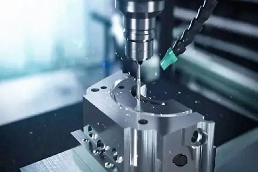
Thin-wall finishing: light radial engagement, coolant at pressure, and a toolpath that balances cutting force on both sides of the wall.
Topology optimisation produces shapes that are efficient and awkward: organic ribs, varying wall sections, pockets where a fixture would like to sit. Machining them without distortion takes three things working in sequence.
Predict before cutting. A 1.2 mm wall warps because cutting force pushes it, so the force is simulated with finite element analysis and the toolpath is adjusted to keep deflection inside roughly ±0.1 mm before the first pass is made.
Sequence for stability, not for speed of removal. The part is taken to a semi-finished state with equal stock allowance all round, which is the state in which it is stiffest and most predictable. Contouring then finishes with radial engagement and climb milling so the wall is cut with balanced force rather than being pushed from one side.
Measure, then compensate. Simulation cannot capture every residual stress, so after semi-finishing the critical dimensions are probed on the machine and the finishing toolpath is shifted to correct for spring-back and drift. That closed loop is what keeps distortion under about 0.05 mm on walls that thin, and it happens before the part is unclamped, when a correction is still possible.
Seals, Bores and Repeatability on EV Components
EV parts add two requirements that ordinary machined components do not have: fluid tightness and rotational accuracy.
- Motor housing water jackets. The sealing area is machined in one continuous five-axis move with no joint or re-clamp in the sealing path, because a joint is a leak path. Flatness is checked by in-process probing, to about 0.01 mm, before the part is released from the fixture.
- Reducer bearing bores. Cylindricity has to sit under about 0.008 mm, and at that level thermal deflection is the limiting factor rather than the tool. Bores are machined in a temperature-controlled environment held to 20 °C ±1 °C, and the final finishing pass only runs after the workpiece has stabilised thermally.
- Volume repeatability. First-pass yield in the high nineties comes from closing the loop: CMM data from finished parts feeds back into the machine so parameters track tool wear and temperature rather than being fixed at program release.
What the Cycle-Time Numbers Look Like
Consolidating operations changes the numbers rather than nudging them. The table below shows a typical gearbox-housing program before and after moving to a single-setup five-axis process — illustrative figures from that production study rather than a quotation for your part:
| Measure | Multi-setup sequence | Single-setup 5-axis |
|---|---|---|
| Oil channel operations | ||
| Cycle time | ||
| Tool life | ||
| Spindle load | ||
| Operational stability |
The spindle-load figure is the one worth dwelling on. Keeping the load under 80% by cutting more strategically rather than harder is what buys tool life and unattended running, and on a production cell those two are worth more than the cycle time itself.
Holding Micron Accuracy Day to Day
Micron-level results are a maintenance regime rather than a specification. Three controls carry it:
| Control | Method | Target |
|---|---|---|
| Machine calibration | ||
| Dynamic accuracy | ||
| Environment |
Nothing in that list is exotic; what makes it work is doing it on a schedule and acting on the result. A machine that is calibrated and run in a stable environment holds its tolerances between checks, and a part that is probed in process does not need to be reworked after inspection.
Collision Avoidance and Tool Axis Control
The failure modes of five-axis machining are different from those of three-axis work, and they are preventable offline rather than at the machine.
Tool holder, spindle and workpiece are the three collision risks, and the geometry that makes a part worth machining on five axes is the same geometry that puts them close together. Verification software builds a digital twin of machine, fixture and part and simulates the complete program, so interference is flagged and corrected offline. Tool axis control then does the positive half of the job: for each feature the CAM system picks the tool orientation that reaches the surface with the best cutting angle and no collision, and rotates the tool progressively through the move instead of holding one direction.
Long, slender tooling adds deflection and chatter to the list. High length-to-diameter tools run with trochoidal paths and controlled engagement so radial force stays low and the tool does not sing — the same principle that makes thin-wall machining predictable.
Case Note: A 2 m Aluminium Battery Tray
A large battery enclosure shows what the single-setup approach is worth on a real program. The requirement was a sealing face flat to 0.1 mm or better on 6000-series aluminium, at a volume of 50,000 units a year. The previous sequence machined it across six setups, accumulated about 0.3 mm of error, produced a leak rate near 5% and took around eight hours per tray, which put the annual target out of reach.
The rework was structural: one fixture, one setup on a gantry machining centre, with the sealing faces, threaded holes and cooling channels machined in the same clamping. High-speed parameters — spindle speeds around 12,000 rpm and feeds around 15 m/min — kept the cycle short once the part no longer had to be re-datumed.
The measured outcome was a sealing face at 0.08 mm flatness, a leak rate around 0.1%, and a cycle time of about 4.5 hours, which put the 50,000-unit target back in range and removed most of the offline leak testing and rework. Those figures come from that program; treat them as an illustration of what consolidation buys, not as a promise on your geometry.
5-Axis Automotive Machining at SHBD Metal
We machine automotive parts on three-, four- and five-axis centres, from single prototypes and validation builds through to repeat production. Our 5-axis CNC machining service handles parts with angled ports, contoured faces and multiple planes of features in one setup; the broader CNC machining department covers the turning, milling and drilling work around it, and the automotive industry page sets out the parts we run for vehicle programs.
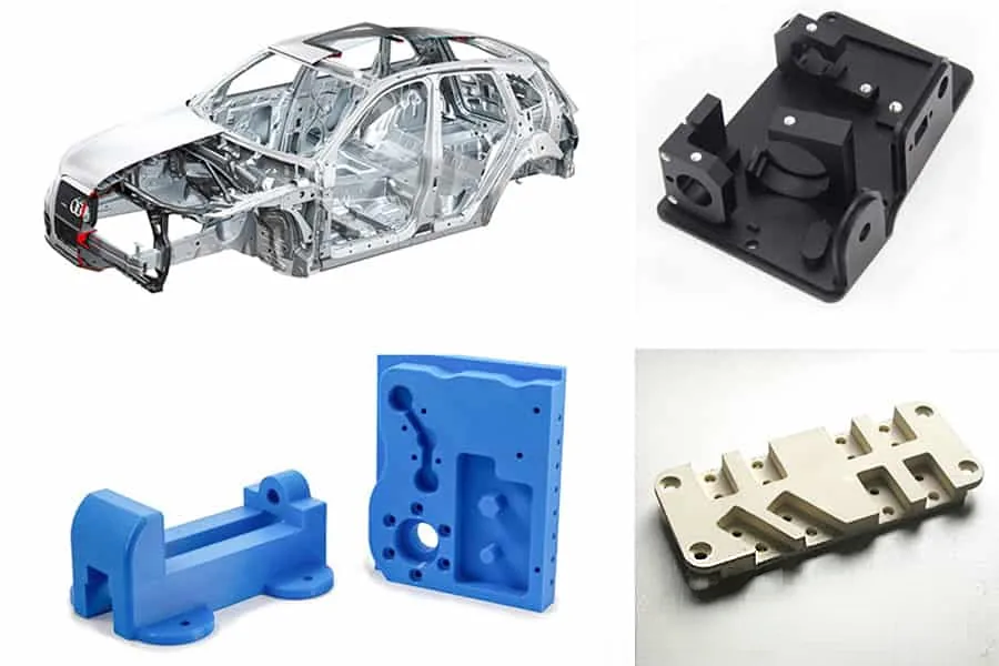
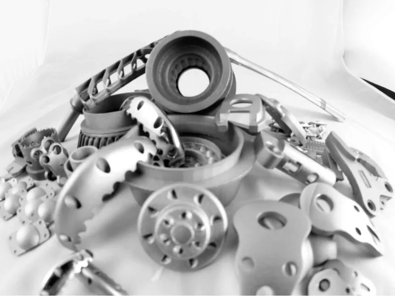
Automotive work from our shop: lightweight structural parts, machined fixtures and a body-in-white reference model.
Verification follows the part: CMM dimensional reports with the shipment, in-process checks on critical features where the program calls for them, and inspection records traced to the batch under our ISO 9001:2015 quality system. Materials and their machinability are listed in the materials library. We work to an ISO 9001:2015 system rather than IATF 16949, so if your program requires a certified automotive QMS from the production supplier, tell us early and we will say plainly whether we fit.
Send the 3D model and the drawing with its critical characteristics and volumes. You get back the process route we propose — how many setups, where the critical datum sits, what we would expect to hold — and a quotation to go with it.
Have an automotive part to machine?
Upload Your CAD FilesFAQs
What does 5-axis machining give over 3-axis for an automotive part?
One setup instead of several. A part with angled ports, contoured faces and pockets on different planes is finished from a single datum, so the error that accumulates every time a part is re-clamped never enters the stack, and features that a three-axis machine can only reach by repositioning are cut in the same operation.
How is consistency maintained in volume production?
Statistical process control on the critical characteristics, targeting a Cpk of 1.67 or better, with machine calibration records behind it. Where the program justifies it, CMM results feed back into the machine so tool wear and thermal drift are compensated automatically rather than discovered at inspection.
How do you stop thin walls from moving during machining?
Prediction first: finite element simulation of the cutting loads shows where a 1.2 mm wall will deflect, and the sequence is set up so stock is removed from both sides evenly. Probing after semi-finishing then measures what actually happened, and the finishing toolpath is shifted to suit, keeping distortion inside roughly 0.05–0.1 mm.
What tolerances are realistic on a large battery tray?
Flatness of the sealing face at 0.1 mm or better across roughly two metres is the working target on 6000-series aluminium. It comes from equal-force clamping, a roughing pass followed by a thermal equalisation hold, and machining the sealing face in the same setup as the threaded holes and cooling channels.
Does an automotive program need IATF 16949?
Tier-one production programs frequently require IATF 16949 from the supplier, so it is worth settling that requirement with the program before tooling is cut. We work to an ISO 9001:2015 system and can supply the process documentation, dimensional reports and SPC data an automotive PPAP submission expects.
How quickly does a 5-axis investment pay back?
On automotive volumes, 12 to 18 months is the usual planning horizon. The payback comes from fewer operations and shorter cycles rather than from the machine's speed alone, which is why the process plan matters as much as the spindle.
Summary
Five-axis machining earns its place in automotive work by removing setups rather than by cutting faster. One datum means the error that accumulates between fixtures never enters the part; the tool axis is free to follow the surface, so topology-optimised and thin-walled shapes become machinable; and probing inside the same setup lets thin walls and sealing faces be corrected while correction is still possible. Add calibration discipline and a stable thermal environment, and a 2 m battery tray or a motor housing can be produced to the tolerances EV programs ask for.