Designing a critical medical monitor or a high-frequency 5G module is profound work. Yet, selecting the wrong PCB circuit board material leads to severe signal degradation, thermal throttling, and ultimately, scrapped validation runs. We manage the complex material science and manufacturing constraints so you can focus entirely on functional innovation and rapid time-to-market.
The Anatomy of a PCB: What Materials Are Used?
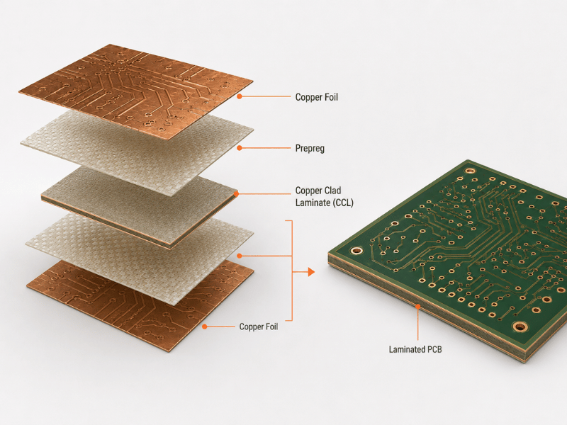
A functional printed circuit board relies on a precisely engineered stack-up of three core elements. Copper foil acts as the conductive pathway, carrying power and high-speed data signals across the board. The Copper Clad Laminate (CCL)provides the rigid or flexible structural backbone of the assembly.
Binding these layers together is the Prepreg, a fiberglass cloth impregnated with uncured resin. During the high-temperature lamination process, this resin melts and cures, permanently insulating and bonding the copper and CCL layers into a monolithic board.
PCB Material Types: A Complete Classification
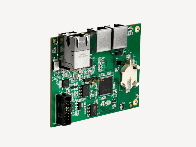
Standard and High-Tg FR4 (pcb fr4 material)
Standard FR4 is a reliable workhorse for consumer electronics, offering an exceptional cost-to-performance ratio for low-frequency, low-power designs. However, standard FR4 substrates expand rapidly under sustained high heat, tearing internal vias apart. If your design undergoes harsh multi-pass lead-free reflow soldering, specify High-Tg FR4 (Tg ≥ 170°C) to prevent barrel cracking and blistering during assembly.
Substrates for High-Speed and RF Applications (PCB material for high-speed design)
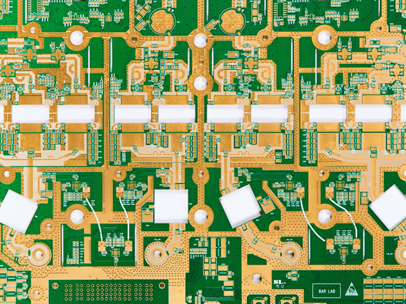
Dropped data packets in an aerospace radar system are catastrophic. Standard FR4 dielectrics absorb excessive energy at microwave frequencies, destroying signal integrity. For 10GHz to 60GHz applications, PTFE and Rogers laminates provide an ultra-low Dissipation Factor (Df) and a stable Dielectric Constant (Dk), ensuring crisp, lossless signal propagation.
Thermal Management: Metal Core PCB Material
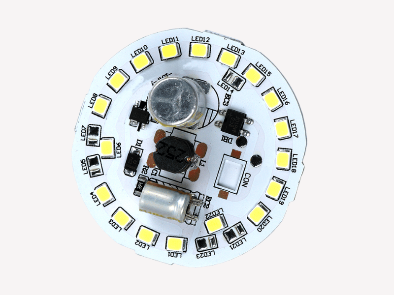
Heavy power LEDs and automotive motor controllers generate intense localized thermal hotspots that standard polymers cannot dissipate. Sustained heat rapidly destroys component lifespans in confined, airless modules. Metal Core PCBs (MCPCB), utilizing an aluminum or copper baseplate, actively draw heat away from critical junctions, significantly extending operating life and preventing field failures.
Extreme Environments: Ceramic PCB Material
In downhole drilling equipment or jet engine sensors, standard organic polymers will melt or chemically degrade. Ceramic PCB materials, such as Alumina ($Al_2O_3$) or Aluminum Nitride (AlN), offer extreme thermal conductivity and true hermetic sealing. These substrates guarantee your control circuits survive extreme temperatures and chemical exposure without losing structural integrity.
Dynamic Applications: Flexible PCB Material
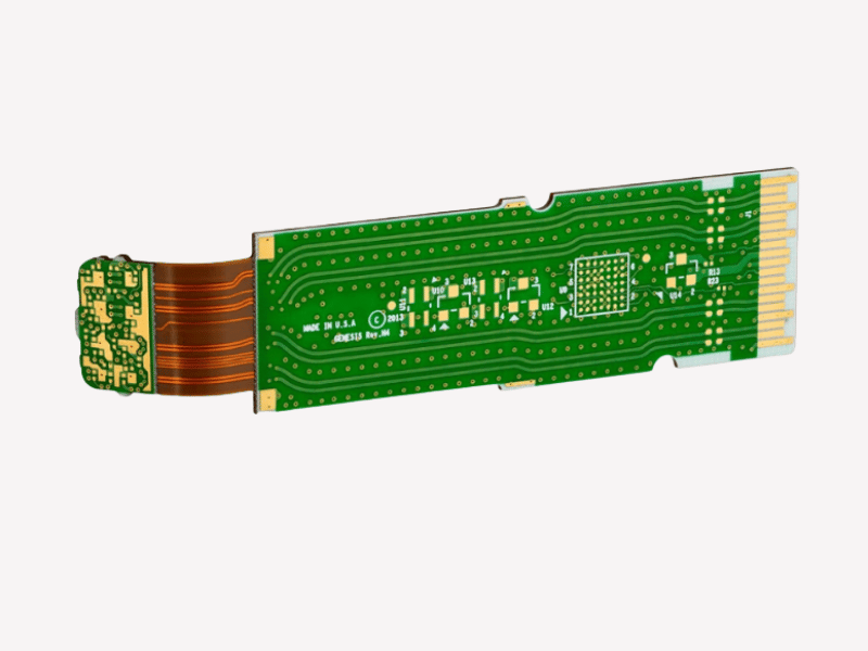
Wearable medical monitors require circuits that contour tightly to human anatomy without fracturing under stress. Flexible PCB materials, primarily Polyimide (PI), endure thousands of dynamic bending cycles while saving critical enclosure space. Integrating them into Rigid-Flex configurations eliminates bulky mechanical connectors, reducing overall weight and eliminating high-risk points of failure.
PCB Material Selection Matrix
| Material Type | Key Characteristics | Cost Impact | Ideal Applications |
| Standard FR4 | Tg ~135°C, Dk ~4.5 | Low | Consumer electronics, simple IoT devices, basic industrial controls. |
| High-Tg FR4 | Tg ≥ 170°C, better thermal stability | Medium | Multi-layer boards, lead-free PCBA, automotive control modules. |
| PTFE / Rogers | Ultra-low Df, stable Dk at high frequencies | High | 5G telecommunications, aerospace radar, high-speed servers. |
| Metal Core (MCPCB) | Thermal Conductivity 1.0 – 3.0 W/m·K | Medium | High-power LED arrays, power converters, automotive lighting. |
| Ceramic | Extreme thermal conductivity (up to 170 W/m·K) | Very High | Heavy industrial sensors, high-pressure environments, aerospace. |
| Polyimide (Flex) | High flexibility, excellent tensile strength | High | Wearable medical devices, compact smartphones, robotics joints. |
4 Key Considerations for Choosing Dielectric Materials
Signal Integrity (Dk & Df)
The dielectric constant (Dk) dictates the speed of your signal, while the dissipation factor (Df) measures the energy lost as heat into the board. High-speed communication buses require materials with a uniformly low Dk across varying frequencies to prevent severe impedance mismatches. Ignoring Df in RF designs guarantees attenuated signals that fail compliance testing.
Power and Heat Dissipation
Always calculate your thermal load before finalizing board routing. If internal copper planes alone cannot handle the targeted wattage, you must upgrade your substrate. Switching to metal-core materials prevents component desoldering and catastrophic thermal runaway in the field.
Manufacturability (DFM)
Exotic materials often demand specialized press cycles, modified drill bit feeds, and distinct chemical plating processes. If you select a hybrid stack-up, differential thermal expansion rates can cause severe board warpage during the lamination cycle. Always verify stack-up viability with your manufacturer before locking your design files.
Material Selections Affecting Cost
High-performance RF substrates like PTFE command premium pricing and generally require longer lead times. You can balance your Bill of Materials (BOM) through hybrid construction techniques. Place expensive high-frequency laminates strictly on the outer signal layers, while maintaining standard FR4 for internal ground and power planes.
Pro Tip: DFM is your Product Insurance
Not sure which material fits your thermal budget? Request RapidDirect’s Free Material Sample Boxtoday. Physically evaluate our high-Tg laminates and metal-core substrates to make risk-free, data-driven decisions for your upcoming design validation.
Seamless NPI: Integrating PCB Fabrication, Sourcing, and Assembly
Specifying high-end PCB materials means nothing if your broker cannot reliably source or process them. Traditional marketplace models introduce severe communication delays and opaque quality control, putting your product launch at risk. We operate as a Tier-1 digital factory, providing direct engineering oversight from design validation to final packaging.
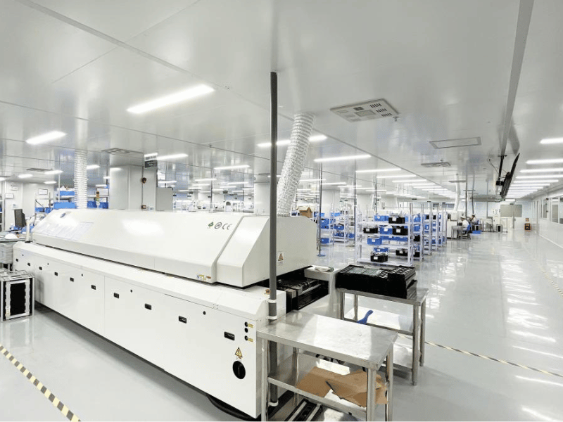
Our expansive facility supports full-cycle NPI, delivering prototype PCBs in as fast as 12 hours with strict IPC Class 2/3 compliance. By combining AI-powered instant quoting with 100% authentic component sourcing and rapid PCBA turnkey assembly, we accelerate your time-to-market. Submit your Gerber files today to receive instant pricing and automated DFM feedback.
Experience our fully integrated EMS Service today. Upload your Gerber and BOM files to our secure platform to receive an instant, transparent quote and a free automated DFM analysis. Let us handle the complex component sourcing and assembly so you can focus entirely on your next design breakthrough.
Frequently Asked Questions (FAQ)
Yes, this process is known as Hybrid PCB construction. Engineers frequently press high-frequency Rogers laminates on the outer signal layers and use cost-effective FR4 for the internal power layers to balance top-tier performance with strict budget constraints.
Tg defines the exact temperature where the rigid resin begins to soften and transition into a rubbery state. For modern lead-free PCBA processes that require higher reflow temperatures, selecting a High-Tg material ensures the board will not delaminate or suffer damaged plated through-holes.