
A pipe joint is decided long before the arc is struck. Bevel angle, land width and root face come off the cutting machine, and whatever error is left there is inherited by every pass that follows. On an automatic or orbital weld, a root face that drifts around the circumference is not a cosmetic problem — it is a lack-of-fusion defect that shows up in radiography, and rework on a prepared heavy-wall joint typically costs several times the original weld.
This guide covers pipe beveling services as a weld preparation discipline: the geometry being cut, why mechanical (cold) severance replaced flame cutting for critical lines, the tolerances that matter for orbital welding, and how heavy-wall and out-of-round pipe are handled without forcing the workpiece into a shape it is not.
What this guide covers
- The job: a machined bevel — angle, land and root face — that gives repeatable penetration and root gap on the first pass.
- The tolerance: ±0.5° on heavy-wall bevel angle, and about ±0.05 mm on root face where the machine measures while cutting.
- The metallurgy: why a flame-cut edge carries a 1–2 mm heat affected layer and mechanical cutting does not.
- The verification: profile gauge, laser scan, dye-penetrant testing, and a profile map per end when the specification asks for it.
What Pipe Beveling Does for a Weld
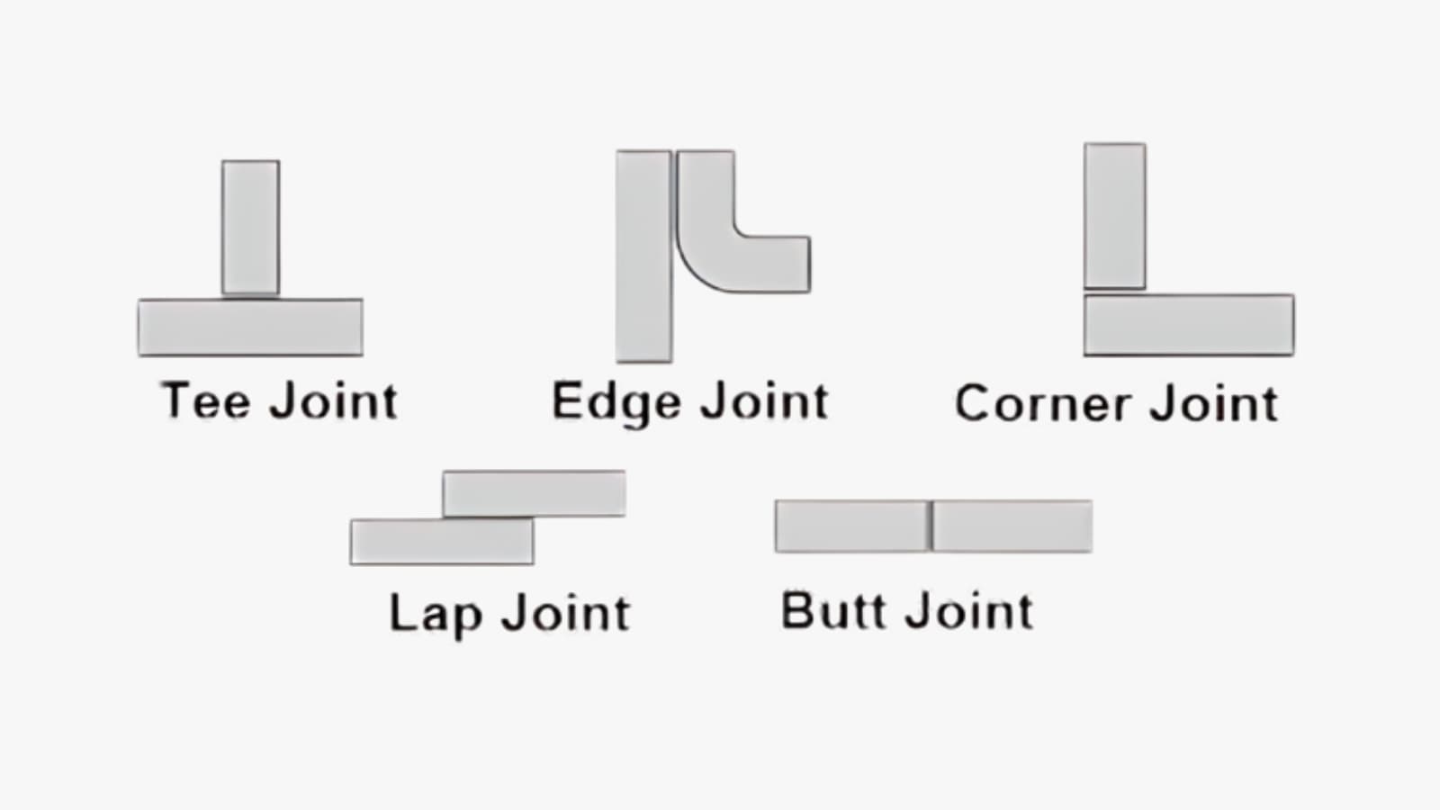
Beveling shapes the pipe end so filler metal can reach the root. A square-cut end closed against its partner leaves no room for the arc: the weld sits on the surface, penetration is shallow, and the joint carries a fraction of the pipe's rating. Cut a bevel and the same two ends open a groove that the root pass can fill from the inside out.
What makes it a service rather than a cut is repeatability. Every end in a spool must present the same angle, the same land and the same face squareness, because the welding procedure specification is written for one geometry. Change the geometry between ends and the welder — or the orbital head — has to adjust parameters mid-spool, which is where porosity and lack of fusion begin.
Three features control the outcome: the bevel angle sets how much weld metal the groove needs; the land, or root face, controls how the root pass bites; and face squareness against the pipe axis decides whether the two ends meet evenly or gap on one side.
Bevel Geometry: Angle, Land and Root Face
The table below is the quick reference we work from when a specification arrives, and the checks that follow each one:
| Requirement | How it is delivered | Why it matters |
|---|---|---|
| Bevel angle and land consistency | ||
| Face squareness and alignment | ||
| Burr and sharp edge removal | ||
| Material-specific tooling | ||
| Shop and field capability | ||
| Welded result |
The angle itself depends on the joint design. A single V at 37.5° is the familiar default for standard wall pipe; thicker walls move to a compound or double-V bevel to cut weld volume; and high-pressure work moves to a U-groove where the root geometry is chosen by analysis rather than habit.
Cold Cutting Versus Thermal Beveling
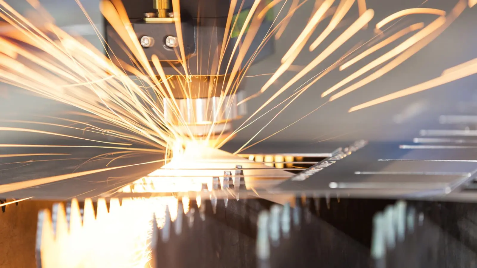
Flame and plasma cutting are fast and convenient, and they leave a metallurgical signature at the cut edge. Heating metal and letting it cool quickly reforms the structure in a narrow band: a heat affected zone one to two millimetres deep, harder and more brittle than the parent metal, and frequently carrying micro-cracks from the cut itself.
Under cyclic pressure that band is where cracks start, because it is hard, it is thin, and it sits exactly where the weld's residual stress concentrates. Mechanical severance removes the problem rather than managing it: high-force cutting and machining produce no phase transition at all, so the weld meets ductile parent metal with its original structure and no brittle layer to propagate from.
The second advantage is dimensional. A computer-controlled cold beveling head runs from a measured model of the pipe end, so the bevel angle and surface finish come out consistent end after end — which is what holds root gap and penetration steady rather than relying on the operator's hand.
Verification runs in two levels. Dye-penetrant testing confirms the beveled face is free of micro-cracks, and a material certificate ties the piece back to its heat lot, so the edge's provenance is documented rather than assumed.
Holding ±0.5° on Heavy-Wall Pipe
Heavy-wall pipe is where bevel discipline becomes measurable. Three practices carry the tolerance:
1. Measure the end before cutting it. A 3D laser scan of the pipe end establishes a digital benchmark. Raw pipe varies — ovality, wall thickness, the direction the end faces — and cutting to a nominal centreline simply transfers that variation into the bevel. Cutting from the measured geometry removes it.
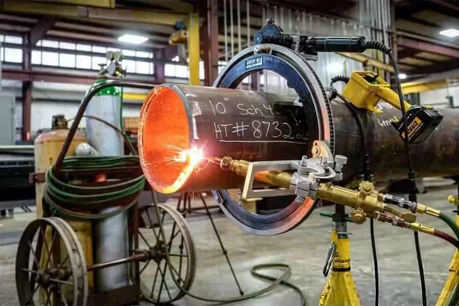
A measured end, clamped without forcing it round: the head follows the pipe's real axis, not a theoretical one.
2. Take the wall off in passes. A single heavy cut on a thick wall dumps heat and load into the edge in one go, which distorts both the geometry and the near-surface structure. Roughing, semi-finishing and finishing passes spread that load, holding angle and surface condition in the same operation.
3. Verify against the procedure, by a person. After machining, a profile gauge reading and a laser scan are compared with the project's welding procedure specification by a qualified engineer. That sign-off is what turns a machined end into a documented weld prep, and it is the step that catches a drift before it reaches the fitter.
Why Orbital Welding Demands Bevel Consistency
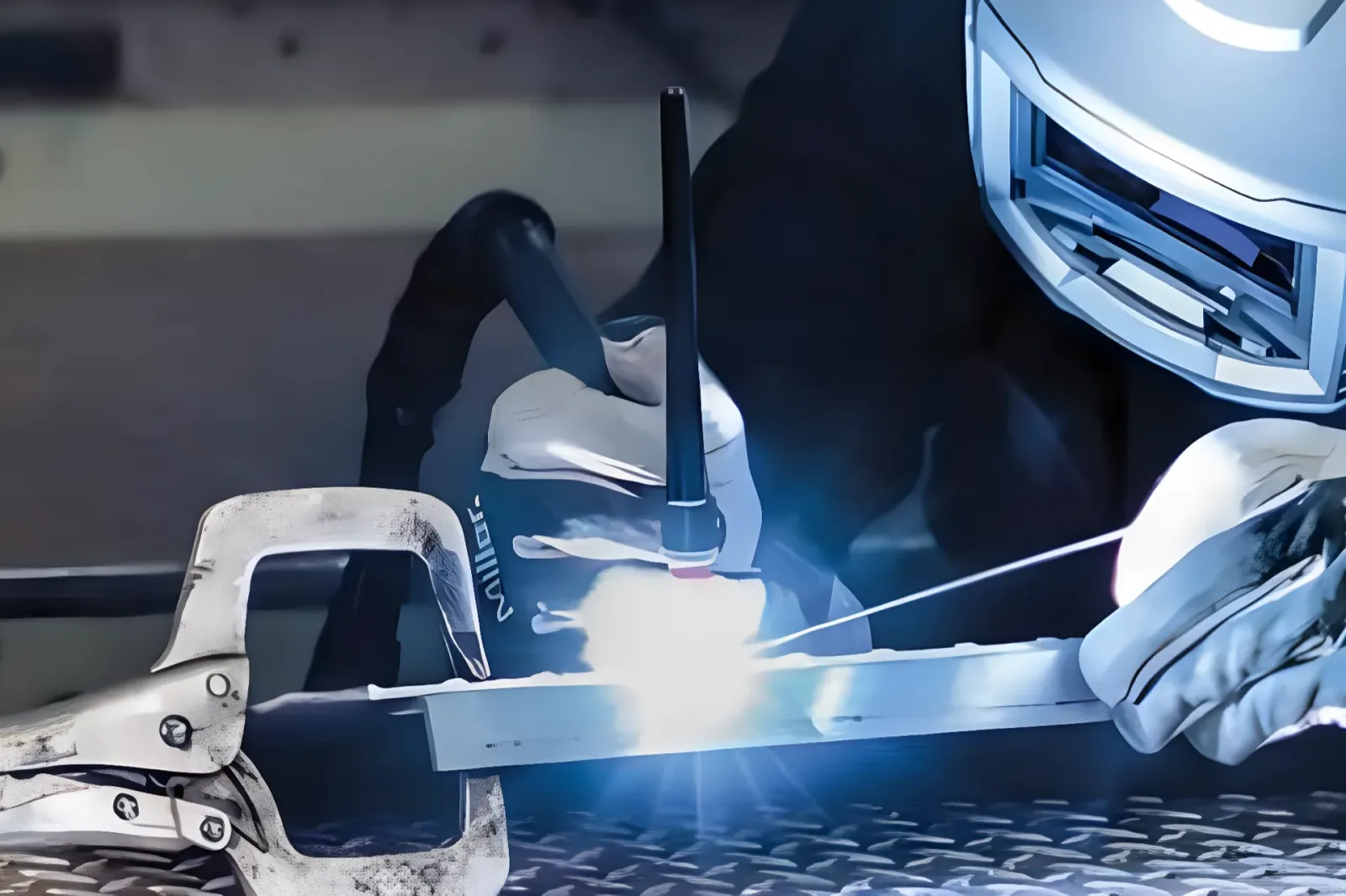
An orbital head runs a program. It does not watch the root gap and it cannot feather a pass when the land runs thick on one side, so any geometric variation in the joint has to be absorbed by parameters that were set before the head started moving. That is why joint preparation matters more for automated welding than for manual work.
The technique that closes the loop is measuring the root face during the cut rather than after it. Where a laser metrology system reports the root face to the control while the bevel is being machined, tool paths correct in real time and the land can be held to roughly ±0.05 mm. On thick material the same feedback is used between rotations, so each pass starts from a measured condition instead of an assumed one.
Documentation follows the same logic. A laser scan after machining produces a 3D profile map of each bevel, which is the evidence an automated welding qualification needs: not a claim that the geometry is consistent, but a per-part record of how consistent it was.
U-Groove Preparation for High-Pressure Service
Deep water and high-pressure service changes the groove shape. A standard V leaves a wide, tapering groove that takes a large volume of filler and concentrates stress at the root; a U-groove with a defined root radius distributes that stress and needs less weld metal to fill.
The route we follow starts with a DFM study of the pipe: material, wall thickness, operating pressure and the loads the joint will see. Finite element analysis selects the root face width, groove angle and radius that minimise stress concentration for that combination, and the profile is then machined by contouring with a form-ground tool of the chosen radius, kept in continuous engagement so the groove comes out as designed rather than approximated.
Validation is dimensional: a contour gauge plus laser scanning confirm that critical features, including the root radius, sit inside a ±0.1 mm band. Because the groove is narrower than a V, the same joint typically consumes about 25% less weld metal — which is time as well as consumables on a thick-wall joint.
Large Diameter Pipe: Cutting From the Real Axis
Large diameter, heavy wall pipe sags under its own weight, and handling adds more. The end is rarely the circle the drawing assumes, so a bevel machined from a theoretical centreline comes out eccentric: the faces do not meet cleanly, the fitter pulls them together, and the joint carries locked-in stress before the first pass.
The fix is to measure the true axis and cut to it. Laser scanning of the inner and outer surfaces produces a 3D model of the end that includes its ovality, and a self-centering clamp designed around that scan holds the pipe without deforming it back into an artificial circle. The CNC toolpath is then programmed adaptively from the same data, so the bevel face comes out concentric to the pipe's real axis — on the pipe that exists, not the pipe in the model.
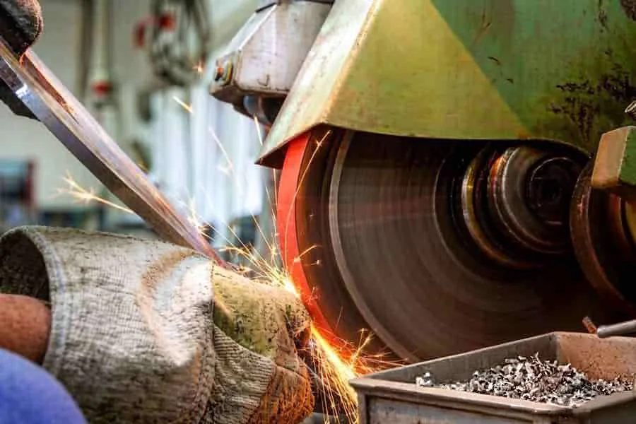
Edge finishing after the bevel pass: a deburred, uniform face is what lets the two ends meet without being pulled into alignment.
This is the difference between accuracy and assumption. Cutting from measured geometry means the ends align on the first fit-up, which matters most on expensive piping that cannot be forced into place without adding stress to the finished weld.
Exotic Alloys and High-Strength Steel
Duplex stainless, high-chromium grades and high-strength steels punish the wrong cutting parameters. Feeds that are too light rub the surface instead of cutting it, which work hardens the edge; heat that lingers depletes chromium at the surface that is about to be welded.
Three controls handle it:
- Parameters from a database, not from habit. Geometry, feed and cutting speed are selected per alloy so the chip stays continuous. A continuous chip carries heat away in the swarf and breaks up the work-hardened layer instead of burnishing it.
- A coolant-fed finish pass. Precision tooling with high-pressure coolant holds surface roughness at Ra 3.2 µm or finer on the beveled face.
- A verification report per piece. Measurements and visual inspection results are recorded, so the edge condition is documented rather than described.
Chromium depletion is the specific hazard on high-chromium stainless. Since a mechanical cut introduces no heat cycle, the chromium at the edge stays where it is, and the corrosion resistance of the joint is not spent before the weld is even made.
Bevel Quality and Long-Term Maintenance
Most piping failures that look like weld failures started at the bevel. Stress corrosion cracking needs three things — tensile stress, a corrosive environment and a susceptible microstructure — and a rough, hardened, micro-cracked edge supplies all three at the point of highest stress.
That makes surface condition a design variable rather than a finishing detail. Bevels finished to Ra 3.2 µm or better with honed tooling leave no initiation sites on the weld-prep face, and a cold-cut edge carries no brittle layer beneath it. In comparative service testing, edges left at typical flame-cut roughness (above Ra 6.3 µm) crack measurably sooner than refined edges under the same conditions.
The commercial argument follows: preparation is a small line item next to the cost of a joint that has to be cut out in service, and it is the cheapest place to prevent cracking.
Case Note: 40 mm S355 Offshore Risers
A representative program from offshore work shows how the geometry and metallurgy decisions interact. A riser fabricator on 40 mm S355 pipe was seeing a rejection rate of roughly 12% in hydrostatic testing, with cracks traced to the hard brittle layer left by flame-cut bevels on the riser ends.
The change was a process substitution rather than a parameter tweak: compound bevels machined cold on a double-bevel cutter, with no heat affected zone at the edge, plus an in-line ultrasonic thickness gauge feeding wall-thickness data back to the control so the bevel geometry adapted to actual wall variation rather than nominal.
With no HAZ to initiate from and a consistent face to weld against, first-pass acceptance on radiography and ultrasonic testing rose into the high nineties, and field welding time dropped substantially because fit-up and repair loops disappeared. The figures above are from that program, quoted here as an industry example rather than as a guarantee on your pipe.
Bevel and Weld Prep at SHBD Metal
We prepare pipe and heavy-wall ends on CNC equipment rather than by hand, so the bevel angle, land and face squareness come from a program and come out consistent end to end. Bevels are deburred and finished as part of the operation, checked with a profile gauge and documented, and the same shop welds the prepared joints under an ISO 9001:2015 quality system — see our metal welding services for the fabrication side.
For pipe and tube work we also cut and fabricate in-house: tube laser cutting for profiled ends and cut-outs, sheet metal fabrication for the supports and brackets around a spool, and CNC machining where a bevel, counterbore or flange face has to be held to a drawing tolerance. Materials and their weldability are listed in the materials library.
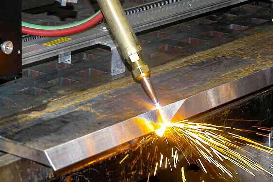
The same edge preparation logic applies to plate: a defined angle and a clean face, whether the bevel is machined for a critical joint or cut thermally for non-critical work.
Send the pipe schedule, the material and the welding procedure specification — or just the drawing with its groove detail. You get back the bevel geometry we propose, the tolerances we will hold, and a quotation with the verification documentation included.
Have pipe ends to bevel?
Send Us the SpecificationFAQs
What bevel tolerance can be held on heavy-wall pipe?
On heavy wall piping the working figure is ±0.5° on the bevel angle, with the land held uniform along the circumference. Where the machine measures the root face during the cut, that dimension tightens to about ±0.05 mm, and every end is checked with a profile gauge and a laser scan before it leaves.
Why is a machined bevel better than a flame-cut one?
Thermal cutting leaves a hardened, brittle layer roughly 1–2 mm deep at the cut edge — the heat affected zone. That layer is where fatigue and stress-corrosion cracks start. Mechanical severance removes the metallurgical change altogether, so the weld meets parent metal that still has its ductility.
Which bevel geometry suits high-pressure piping?
A U-groove, with the root face width, groove angle and radius chosen by finite element analysis for the specific wall thickness and duty. The root radius is held to about ±0.1 mm, and because the groove is narrower than a standard V it uses roughly 25% less weld metal.
Can an out-of-round pipe be beveled concentrically?
Yes, and that is the point of scanning first. Large diameter pipe sags out of round under its own weight, so a bevel cut from a theoretical centreline ends up eccentric. Scanning the inner and outer surface gives the real axis, and an adaptive toolpath machines the bevel concentric to that.
How are duplex and high-chromium grades handled?
Cold cutting keeps the edge chemistry intact, so there is no chromium depletion at the weld zone. Feeds and speeds are set from a parameters database so the chip stays continuous, which stops the surface from work hardening, and a coolant-fed finish pass holds roughness at Ra 3.2 µm or better.
What documentation ships with the bevels?
A dye-penetrant result confirming no micro-cracks on the beveled face, surface roughness readings, a material certificate traced back to the heat lot, and a laser-scan profile map per end where the project calls for one.
Summary
Pipe beveling is where a joint's quality is fixed. Hold the angle and land consistent, cut mechanically instead of thermally so no brittle layer is left at the edge, verify the root face against the welding procedure specification, and machine to the pipe's measured axis rather than its nominal one. Do those four things and the weld passes radiography the first time — on standard wall carbon steel and on a 40 mm offshore riser alike.