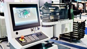

Few questions come up more often in precision manufacturing than how does CNC machining work? The answer is a well-defined sequence of digital and physical steps that transforms a 3D model into a physical part — and understanding that sequence is valuable whether you are a design engineer, a procurement manager, or simply someone who wants to know what happens after you click "upload" on a quote request.
CNC machining is a subtractive manufacturing process: computer-controlled machine tools remove material from a solid block until the remaining shape matches the CAD model. The "CNC" in the name stands for Computer Numerical Control, meaning a computer reads a part program and converts it into coordinated machine motion. No manual cranking, no guesswork — just repeatable, code-driven cutting.
In this article, we break the process down into six steps, from the first CAD sketch to the finished, inspected, and finished part. Along the way, we will look at the machines involved and the quality checks that separate a reliable CNC machining service from one that ships surprises.
What Is CNC Machining?
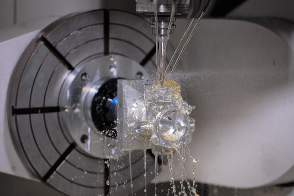
CNC machining is a manufacturing method in which pre-programmed software directs the movement of cutting tools. The machine removes material from a solid workpiece — metal or plastic — in precise increments until the part matches the dimensions defined in the design file. Because the entire sequence is executed from code, CNC machining achieves a level of repeatability that manual machining cannot match, even across runs of thousands of identical parts.
The term covers several operations. Milling uses rotating multi-point cutters to shape flat and contoured surfaces. Turning spins the workpiece against a stationary tool to produce cylindrical features. Drilling, boring, tapping, and grinding round out the family. All share the same core principle: controlled removal of material to achieve specific dimensions, tolerances, and surface finishes.
Step 1: Designing the CAD Model
Every machined part starts as a CAD (Computer-Aided Design) model. The engineer defines the geometry — outer dimensions, holes, pockets, threads, radii — and, ideally, considers manufacturability at the same time: wall thicknesses that the cutter can reach, internal corner radii larger than the tool radius, and features that avoid excessive setups.
The CAD file format matters too. STEP and IGES are the most universal exchange formats, while native files from SolidWorks, Fusion 360, or NX preserve full feature history. A good manufacturing partner will review the model and flag design-for-manufacturability (DFM) issues before any metal is cut, which is why we recommend uploading CAD files rather than 2D drawings alone.
Step 2: Converting CAD to CAM Code
Once the model is finalized, CAM (Computer-Aided Manufacturing) software takes over. CAM programming is where machining strategy is decided: which tools to use, at what spindle speed and feed rate, in what order, and along which tool paths. The software simulates each pass, detects collisions, and then posts the result as G-code — the line-by-line instruction set that the machine controller understands.
This step has an outsized effect on cost and quality. A well-optimized program machines a part in minutes with predictable tool wear; a poorly planned one can double cycle time or leave visible tool marks. Shops that invest in experienced programmers and simulation software deliver better surface finishes and faster lead times for the same design.
Step 3: Machine Setup and Fixturing
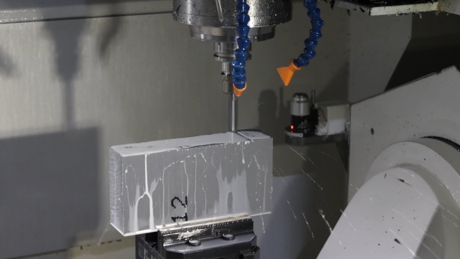
Before cutting begins, the operator prepares the machine. The workpiece is clamped to the table using a vise, fixture, or custom workholding solution, and the part program zero point is established — the reference from which every dimension is measured. Cutting tools are loaded into the spindle or the automatic tool changer, and the controller receives the program.
Setup is where dimensional accuracy is won or lost. If the workpiece shifts under cutting forces, every feature machined after that point is out of position. High-quality shops use torque-controlled clamping, probing cycles that locate the part automatically, and rigid fixtures designed specifically for the geometry being cut.
Step 4: The Machining Process
With setup complete, the machine executes the program. The typical cycle moves through two phases. Roughing removes the bulk of the material quickly, leaving a small amount of stock on the surfaces. Finishing then removes that stock with lighter cuts at higher precision, bringing the part to final dimensions and surface finish.
Throughout the cycle, the machine manages spindle speed, feed rate, and coolant flow automatically. Modern CNC machining centers also monitor spindle load and tool wear, and many can run unattended — a key reason why per-part cost drops so steeply as order quantities increase.
Step 5: Inspection and Quality Control
Machining does not end when the last tool path completes. The part must be verified against the drawing. Dimensional inspection typically uses calipers, micrometers, and pins for simple features, and coordinate measuring machines (CMMs) for complex geometry and critical datums. Surface roughness is checked with profilometers, and thread gauges verify internal threads.
For aerospace, medical, and safety-critical parts, inspection is often documented part by part, with reports shipped alongside the order. A mature quality assurance process — calibrated equipment, trained inspectors, and full traceability — is the difference between a supplier you can trust and one you have to re-check yourself.
Step 6: Post-Processing and Finishing
Many parts go to secondary operations after machining. Deburring removes the sharp edges left by cutting tools. Bead blasting or tumbling improves surface uniformity. Anodizing, plating, and powder coating add corrosion resistance or color. Heat treatment adjusts mechanical properties, and assembly brings machined components together with fasteners or adhesives.
Finishing decisions should be made early — ideally during the DFM review — because they affect tolerances and cost. Anodizing, for example, adds a few microns of coating that can shift tight dimensions, and threaded holes must be protected or plugged before plating. A supplier that coordinates machining and finishing under one roof eliminates the hand-off risks that plague multi-vendor projects.
Common Types of CNC Machines
Understanding how CNC machining works also means knowing which machine does what:
- CNC milling machines — rotating cutters, stationary workpiece; the default for housings, brackets, and complex 3D shapes.
- CNC lathes — rotating workpiece, stationary tool; ideal for shafts, bushings, and other cylindrical parts.
- Swiss-type lathes — sliding-headstock lathes that machine tiny, complex components in one pass.
- CNC grinders — abrasive wheels for sub-micron finishes and hardened materials.
- EDM machines — electrical discharge machining for hard materials and fine internal detail.
Most precision parts use two or more of these in sequence. A component might be turned, then milled for flats and holes, then ground on a critical diameter — all under one quality system when you work with a full-service manufacturer.
Frequently Asked Questions
How long does CNC machining take?
Lead time depends on complexity, material, and quantity. Simple prototypes can be machined and shipped within days; production runs of complex parts typically take one to three weeks. Programming and setup dominate the timeline for small quantities, which is why prototypes benefit from fast-quote services with DFM feedback.
What file formats are needed for CNC machining?
STEP and IGES are the most reliable neutral formats. Native CAD files, 2D drawings with tolerances, and STL files can also be used. A PDF drawing specifying tolerances, threads, and surface finish requirements is always a helpful supplement to the 3D model.
What tolerances can CNC machining hold?
Standard machining holds ±0.025 mm to ±0.05 mm; precision work reaches ±0.005 mm on critical features. Tolerance requirements directly affect cost, so it pays to specify only the tolerances the application actually needs.
Is CNC machining suitable for prototyping?
Yes. CNC machining produces prototypes in the same material and with the same mechanical properties as production parts, which makes it ideal for functional testing. Many teams prototype with CNC machining and then move to injection molding or die casting once the design is validated.
Can CNC machined parts be finished after machining?
Almost always. Anodizing, plating, powder coating, painting, bead blasting, and polishing are common post-machining processes, each adding specific surface properties. See our materials and finishing resources for guidance on matching finishes to applications.
Get Your CNC Machining Quote
Now that you know how CNC machining works, put it to work for your project. SHBD Metal operates 3-axis, 4-axis, and 5-axis machining centers alongside CNC turning and Swiss-type lathes, with in-house finishing and documented inspection on every order. Our engineers review your design for manufacturability before cutting begins — so the quote you receive reflects a part that can actually be built, on time and to spec.
Upload your CAD files today and receive a detailed quote within hours. From a single prototype to a production run of thousands, we are ready to help you bring your design to life.