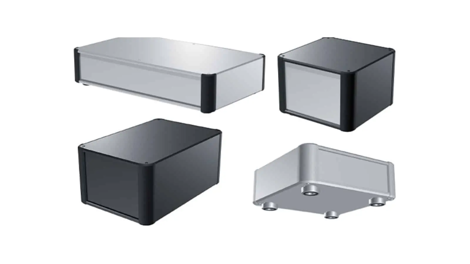

Metal fabrication is how raw sheet, plate, tube, and bar stock becomes the brackets, enclosures, chassis, and structural components that hold the physical world together. Before any laser fires or any press brake cycles, however, someone has to make a series of design decisions that determine whether the part is cheap and repeatable — or expensive and trouble-prone. That decision-making process is metal fabrication design.
For procurement managers and design engineers sourcing custom parts, understanding the fundamentals of fabrication design is not optional. The geometry you put on the drawing board directly controls tooling cost, cycle time, tolerance capability, and scrap rate. This guide walks through the core processes, the design-for-manufacturability (DFM) rules that matter most, and the practical trade-offs that separate a smooth production run from a costly revision loop.
At SHBD Metal, we combine laser cutting, CNC punching, press braking, welding, and finishing under one roof, backed by an in-house engineering team that reviews every design before production starts.
What Is Metal Fabrication Design?
Metal fabrication design is the discipline of designing parts and assemblies so they can be manufactured efficiently using fabrication processes — cutting, bending, forming, joining, and finishing. It is part of the broader design-for-manufacturability family, but it has its own rules because fabrication is fundamentally different from machining or molding.
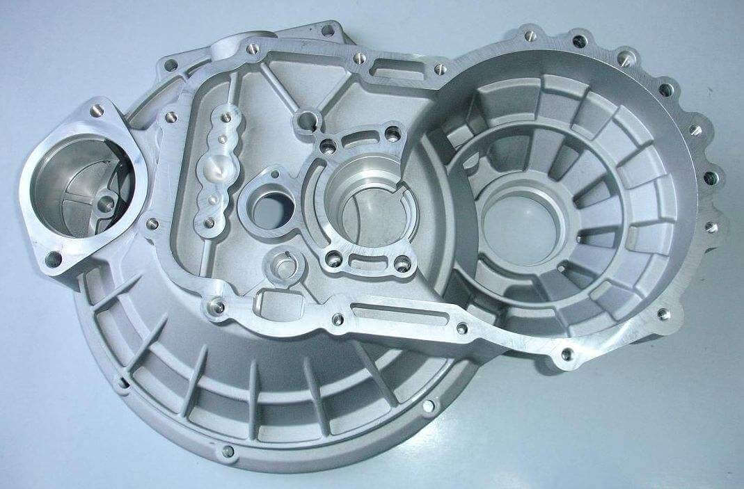
Unlike CNC machining, which removes material from a solid block, fabrication starts with flat sheet stock and changes its shape. That means the design rules revolve around bend allowances, grain direction, minimum bend radii, hole-to-bend distances, and weld access — parameters that simply do not exist in subtractive machining. Getting these right at the design stage keeps parts flat, square, and within tolerance when they come off the line.
A well-executed fabrication design answers three questions before a single part is produced: Can the geometry be cut efficiently? Can it be formed without cracking or springback issues? And can it be assembled and finished cost-effectively?
Core Metal Fabrication Processes
Every fabricated part passes through a sequence of operations. Understanding each step helps you specify parts correctly and anticipate where cost and lead time accumulate.
Cutting
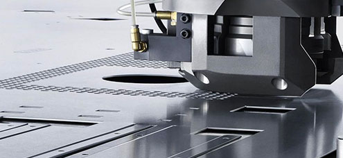
Cutting separates the flat blank from the sheet. The dominant methods in modern fabrication shops are laser cutting, plasma cutting, waterjet cutting, and CNC punching.
- Laser cutting delivers tight tolerances (±0.1 mm or better) and clean edges on materials up to roughly 25 mm thick, with minimal heat-affected zone.
- Plasma cutting is faster and cheaper on thick carbon steel plate, with a wider kerf and slightly rougher edges.
- Waterjet cutting cuts without heat, making it the right choice for materials that distort under thermal input, such as aluminum, titanium, and thick stainless steel.
- CNC punching excels at high-volume parts with repeated hole patterns, where tooling amortizes quickly.
Bending and Forming
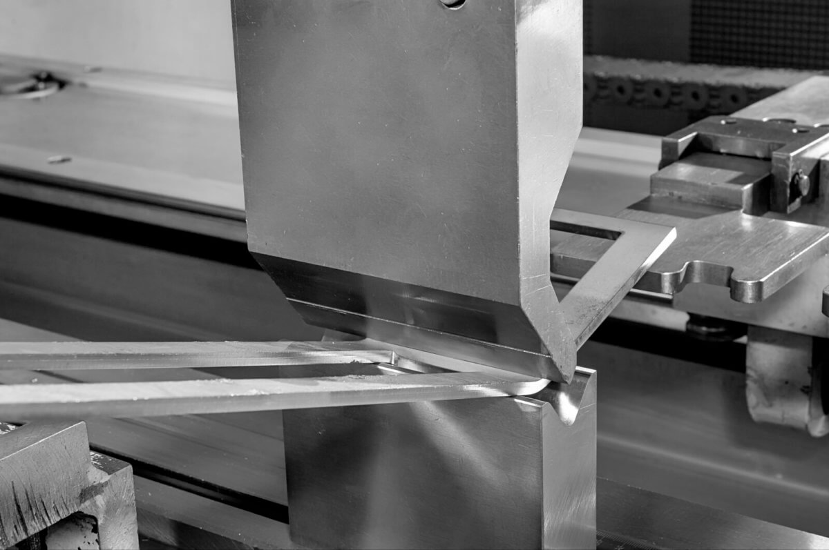
Bending turns flat blanks into 3D shapes. The press brake applies force through a punch and die to create a bend along a straight line. Key design parameters include the bend radius, bend allowance, and minimum flange length. Forming — including stamping, roll forming, and spinning — goes further, reshaping the material with dedicated dies or progressive tooling.
Two rules dominate bend design. First, the inside bend radius should be at least one material thickness; tighter radii risk cracking, especially across the grain. Second, features such as holes and slots must stay clear of the bend line — typically at least two to three times the material thickness — or they will distort as the metal flows.
Joining and Welding
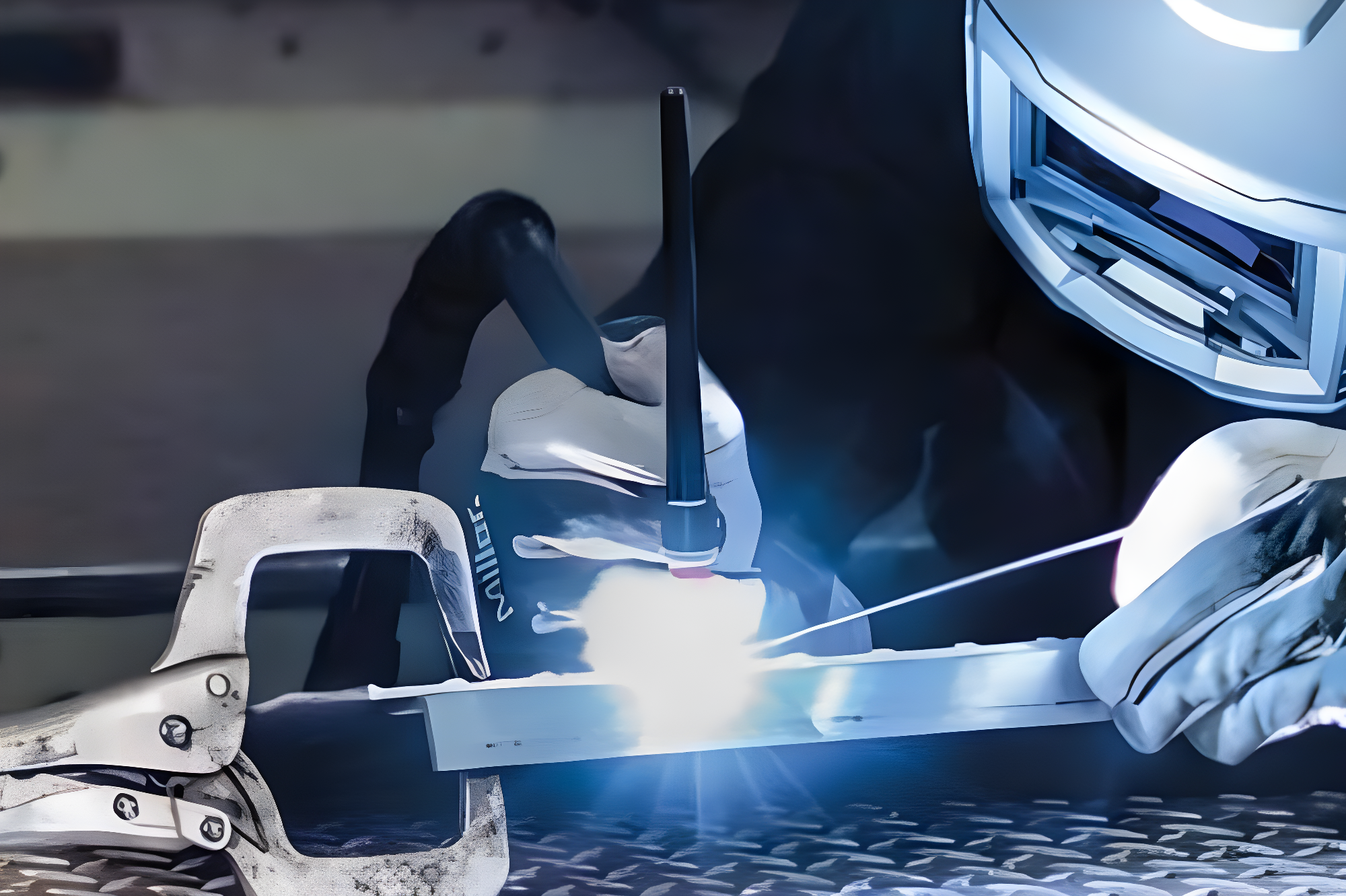
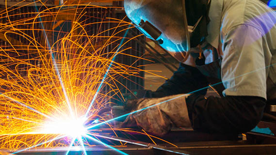
Where one piece of sheet metal is not enough, parts are joined. Welding is the most common permanent method: MIG and TIG welding handle most steel, stainless, and aluminum assemblies. Rivets, clinching, and self-clinching fasteners join parts without heat, which preserves coatings and avoids distortion. Hardware such as PEM inserts is pressed in place so threads survive in thin sheet.
For design purposes, remember that welded assemblies accumulate tolerance. Each weld joint introduces shrinkage and distortion, so critical dimensions should be referenced from a single datum, and generous tolerances should be allowed across welded features. Where possible, design the assembly so welding happens before machining critical faces.
DFM Rules for Metal Fabrication Design
These are the rules our engineers apply to every fabrication drawing that comes across the desk. Following them at the design stage is the single fastest way to reduce cost and shorten lead time.
- Maintain uniform material thickness. Fabrication starts with standard sheet gauges. Designing around common thicknesses — 1.0, 1.5, 2.0, 3.0 mm — avoids special-order material.
- Specify a minimum inside bend radius of one material thickness. Tighter bends require special tooling or risk fracture.
- Keep holes and slots at least 2× material thickness from bend lines and edges. Otherwise the features deform or the edge tears.
- Use standard hole sizes. Punch tooling is sized in standard increments; a non-standard hole means a custom tool or a secondary drilling operation.
- Avoid complex cutouts that require tight corner radii. Laser-cut corners should carry at least 0.5 mm radius; sharp internal corners concentrate stress and slow cutting.
- Design for the finished assembly. Consider whether welds are accessible, whether fasteners can be installed, and how the part nests on the sheet for optimal material utilization.
Material Selection for Fabricated Parts
Material choice drives both performance and cost in fabrication. Mild steel is the workhorse: strong, weldable, and inexpensive, though it requires paint or plating for corrosion resistance. Stainless steel adds corrosion resistance for food, medical, and outdoor applications. Aluminum offers light weight and good thermal performance, while brass and copper bring conductivity and aesthetics for electrical and architectural parts.
Thickness and temper matter as much as alloy family. A harder temper holds tighter tolerances after forming but is more likely to crack at tight radii. If you are unsure which material best fits your application, compare the mechanical properties and availability of common grades in our materials guide.
Balancing Cost, Quality, and Lead Time
Fabrication cost is driven by material utilization, operation count, and tolerances. A design that nests efficiently on a standard sheet can cut material cost by 20–30 percent. Every additional operation — deburring, countersinking, welding, finishing — adds handling time and cost. Tight tolerances force slower cutting speeds and more inspection, so only call out what the application actually needs.
For parts that combine fabricated and machined features — for example, a sheet metal enclosure with precision-machined mounting bosses — plan the process sequence carefully. A single supplier that handles both fabrication and CNC machining saves you logistics, tolerance-stacking risk, and coordination overhead.
Quality Control and Inspection
Fabricated parts must be verified, not just assumed. Dimensional inspection confirms hole positions, bend angles, and flatness; surface inspection checks for scratches, burrs, and weld defects. For painted or plated parts, coating thickness and adhesion are verified. When parts carry safety-critical or regulatory requirements, full inspection reports with CMM data and material certificates become part of the deliverable. See our quality assurance process for the inspection capability we apply to every fabrication order.
Frequently Asked Questions
What is the difference between metal fabrication and CNC machining?
Metal fabrication transforms flat sheet, plate, or tube stock through cutting, bending, forming, and joining. CNC machining removes material from a solid block with rotating cutting tools. Many products use both: fabricated enclosures and frames combined with machined inserts, bosses, and precision features.
What is the minimum bend radius for sheet metal?
As a general rule, the inside bend radius should be at least one times the material thickness. Softer materials such as aluminum 5052 and low-carbon steel can often bend tighter, while harder tempers and thicker gauges need larger radii to avoid cracking.
How far should holes be from a bend line?
Holes and cutouts should stay at least two to three times the material thickness away from a bend line. Closer than that and the hole will distort as the material stretches during bending.
What materials can be metal fabricated?
Mild steel, stainless steel, aluminum, brass, copper, and specialty alloys are all routinely fabricated. The best choice depends on strength, corrosion resistance, weight, conductivity, and budget. Compare common grades in our materials guide before you finalize the design.
Can fabricated parts meet tight tolerances?
Yes. Laser-cut features hold ±0.1 mm, and bend dimensions typically hold ±0.2–0.5 mm depending on material and geometry. If your application needs tighter precision, machined features or post-fabrication machining can be added where required.
Get Your Metal Fabrication Quote
Great metal fabrication design is the cheapest insurance your project can buy. At SHBD Metal, our engineers review every drawing for manufacturability, suggest cost-saving geometry, and handle cutting, forming, welding, finishing, and inspection in one facility — with clear documentation at every step.
Upload your CAD files today and receive a detailed quote within hours. From single prototypes to full production runs, we are ready to turn your design into parts.