
When the project calls for metal components with complex geometries and tight tolerances, two manufacturing processes typically rise to the top of the shortlist: Metal Injection Molding (MIM) and Die Casting. Both are high-volume metal-forming methods, but they operate on fundamentally different principles and excel in completely different scenarios.
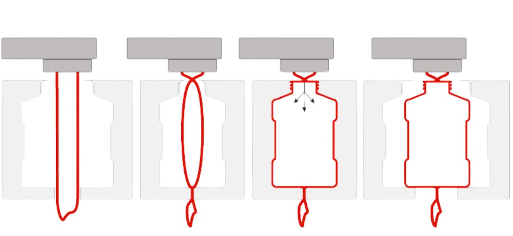
Metal Injection Molding borrows the workflow of plastic injection molding and applies it to metal powders. Fine metal particles are blended with a thermoplastic binder, injected into a mold cavity, then subjected to debinding and sintering to produce fully dense metal parts. Die Casting, by contrast, forces molten metal directly into a steel mold under high pressure, where it solidifies almost immediately into the final shape.
The choice between them is rarely clear-cut. Material selection, part size, dimensional requirements, production volume, and cost targets all tilt the scales one way or the other. This article breaks down every factor so you can make an informed decision for your next project.
Process Fundamentals at a Glance
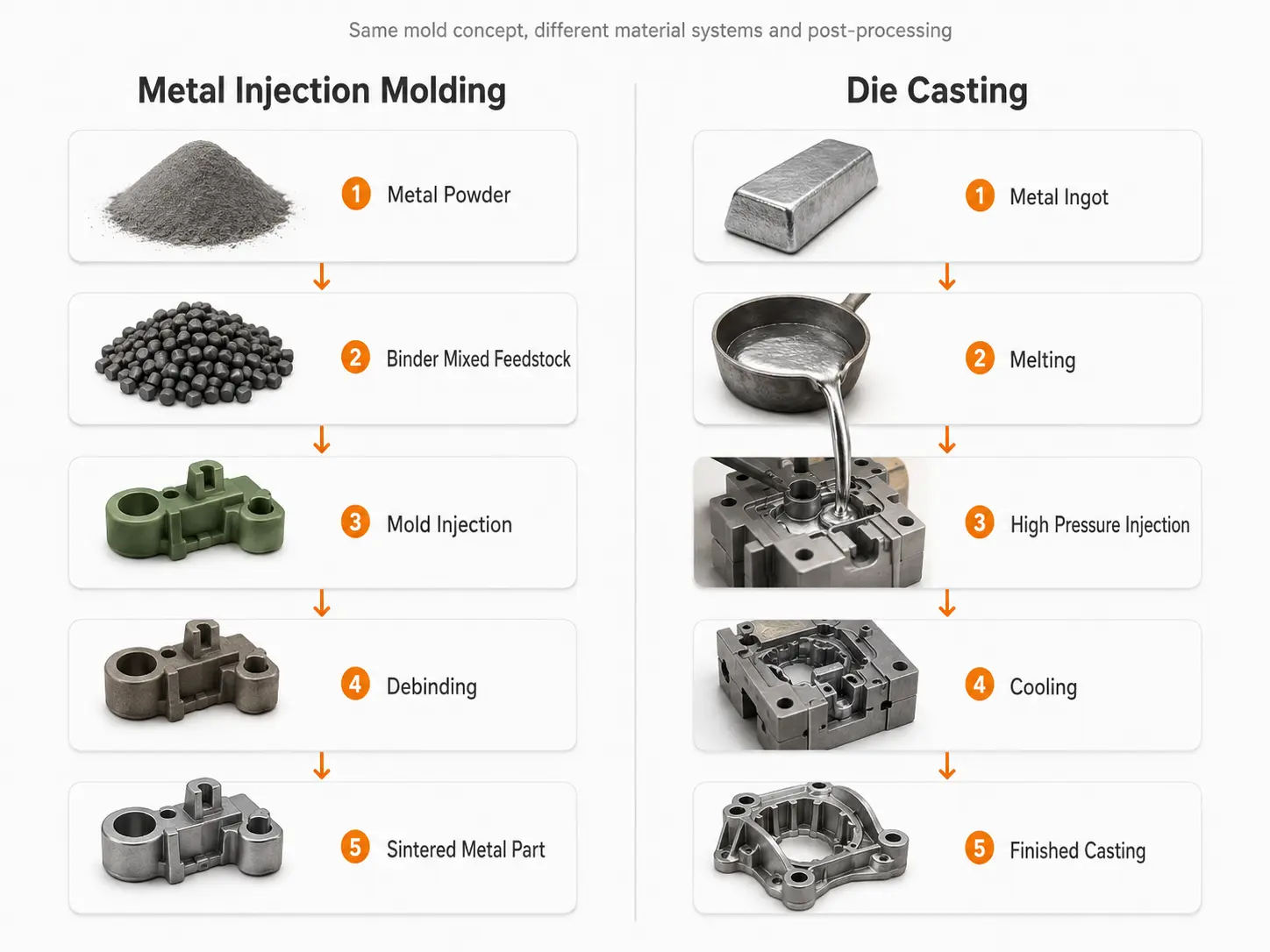
Before comparing performance and cost, it helps to understand what each process actually does inside the machine. The table below summarizes the core differences:
| Parameter | Metal Injection Molding (MIM) | Die Casting |
| Raw Material Form | Fine metal powder (typically < 20 µm) mixed with polymer binder | Molten alloy poured or ladled into shot sleeve |
| Operating Temperature | Binder melts at ~150–200 °C; sintering at 1100–1400 °C | Metal held molten at 600–700 °C (zinc) to 650–750 °C (aluminum) |
| Typical Injection Pressure | 80–200 MPa (comparable to plastic injection) | 10–100 MPa depending on machine type |
| Cycle Time (per cavity) | 30–120 seconds (molding) + 4–12 hours (sintering batch) | Seconds to a few minutes per shot |
| Part Size Range | Less than 0.1 g up to about 300 g (typical); max ~1 kg | A few grams up to 25+ kg for large automotive castings |
| Dimensional Tolerance | ±0.3% to ±0.5% of dimension (after sintering shrinkage) | ±0.1 mm to ±0.5 mm depending on alloy and complexity |
| Surface Finish (Ra) | 0.8–1.6 µm (as-sintered); can be polished further | 1.5–3.0 µm (as-cast); machined surfaces can be finer |
| Secondary Operations | Minimal—near-net shape; deburring or coining occasionally | Trimming, machining, surface coating often required |
| Tooling Cost | $15,000–$80,000 (mold for green part) | $5,000–$150,000 (die set) |
The most striking difference is the thermal journey. In MIM, the metal never melts during molding—only the binder does. Full densification happens in a separate sintering furnace, which means the molding step runs at modest temperatures but the overall cycle includes a long batch sintering phase. Die casting handles molten metal directly, so parts solidify in seconds, but managing flow, turbulence, and porosity becomes a central challenge.
The Material Divide: Your First Filter
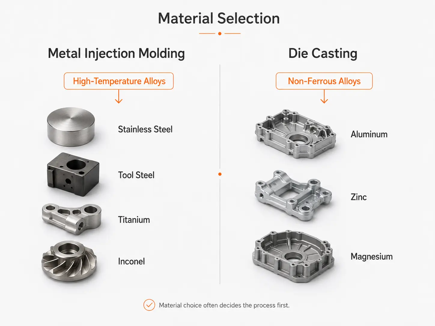
Material compatibility is often the single most decisive factor when choosing between MIM and die casting. The two processes support largely overlapping but distinctly different alloy families.
What MIM Can Process
Because MIM starts from powder, it can handle virtually any metal that can be atomized into fine particles. This includes materials that are difficult or impossible to cast:
- Stainless steels — 316L, 17-4PH, 420, 430L are the most common MIM grades, offering corrosion resistance and strength for medical, automotive, and consumer applications.
- Low-alloy steels — 4140, 4340, and proprietary MIM blends provide high strength after heat treatment, competing with wrought steel properties.
- Tool steels — M2, D2, H13 can be formed into small near-net shapes without the machining difficulty of hardened tool steels.
- Soft magnetic alloys — Fe-Si, Fe-Ni (Permalloy), and Fe-Co alloys for sensor cores and solenoid components.
- Titanium and superalloys — Ti-6Al-4V, Inconel 718, and Hastelloy grades are MIM-processable, though sintering requires high vacuum or controlled atmospheres.
- Copper and precious metals — Used in electronics, thermal management, and jewelry applications.
What Die Casting Can Process
Die casting is limited to alloys with relatively low melting points that can be injected while molten without degrading the steel die:
- Aluminum alloys — A380, A383, ADC12, and A356 dominate the industry. Excellent strength-to-weight ratio, good corrosion resistance, and reasonable cost.
- Zinc alloys — Zamak 3, Zamak 5, ZA-8. Lower melting point (~390 °C) extends die life and allows thinner walls than aluminum.
- Magnesium alloys — AZ91D, AM60B. Lightest structural metal, commonly used in automotive and electronics housings.
- Copper-based alloys — Limited use due to high melting temperature that shortens die life.
- Lead and tin alloys — Specialized applications such as battery terminals and decorative components.
If your part needs to be made from stainless steel, titanium, or tool steel, MIM is almost certainly the right path. If the design calls for a lightweight aluminum housing or a zinc structural bracket at the lowest possible per-part cost, die casting will generally win.
Core Performance Comparison Between MIM and Die Casting
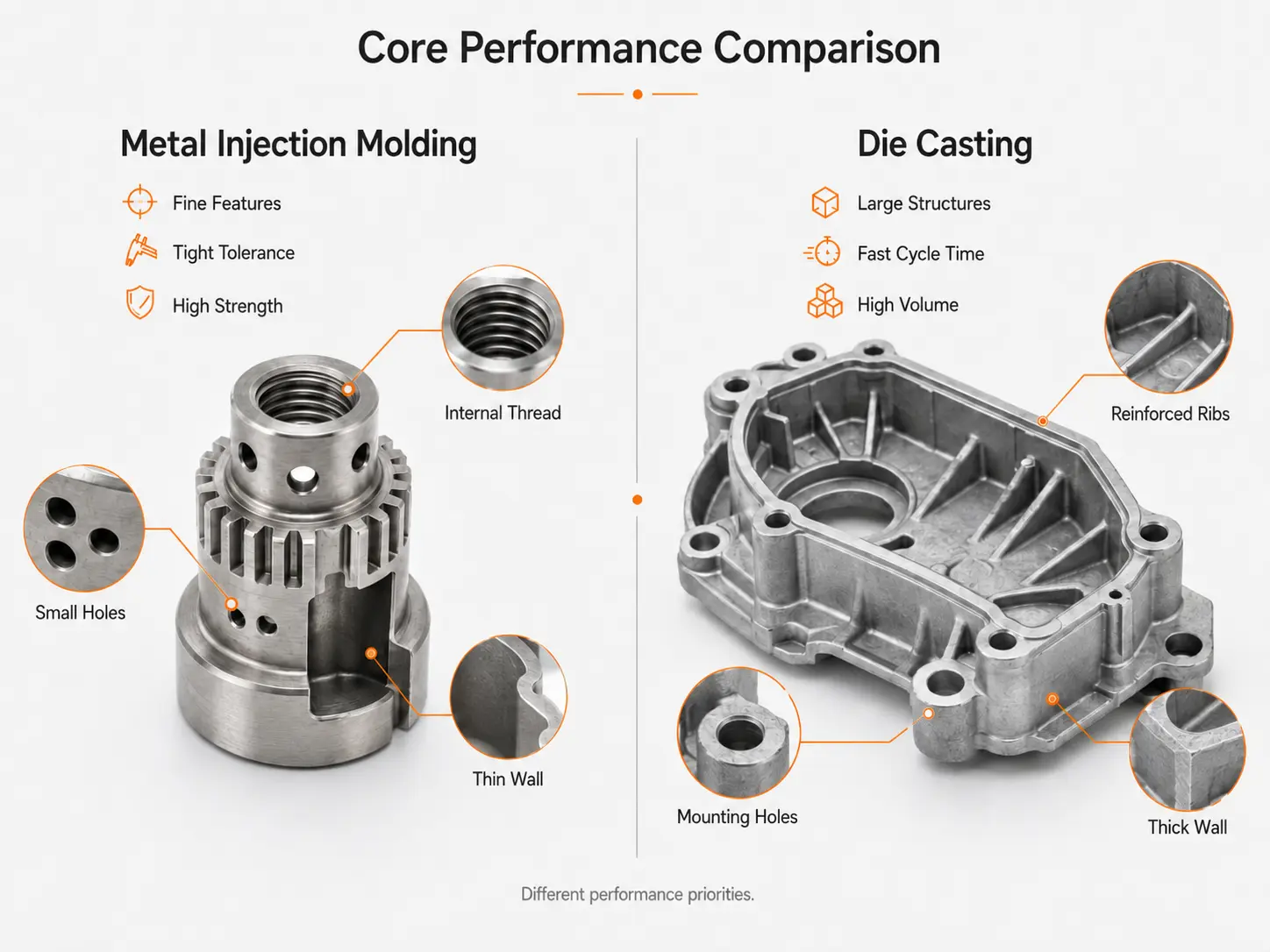
When the material decision is made, the next question is whether the parts produced by each process will meet the application's mechanical and environmental demands.
Mechanical Strength and Density
Properly sintered MIM parts reach 95–99.5% of theoretical density. After sintering, many MIM alloys achieve 90–100% of the mechanical properties of their wrought counterparts. For example, MIM 17-4PH stainless steel can reach ultimate tensile strength of 1100–1300 MPa after heat treatment, matching bar stock. This makes MIM suitable for structural and load-bearing components.
Die cast parts typically contain 0.5–3% porosity due to trapped gas during injection. This limits mechanical properties relative to wrought material. Aluminum die castings like A380 achieve about 320 MPa UTS, which is adequate for many housings, brackets, and non-structural parts, but not for safety-critical or fatigue-loaded applications without extensive quality control.
Corrosion Resistance
MIM parts made from 316L or 17-4PH inherit the full corrosion resistance of the alloy because the sintered structure is dense and homogeneous. Die cast aluminum develops a natural oxide layer that provides reasonable atmospheric corrosion protection, but the porosity can trap moisture and promote localized corrosion in aggressive environments. Zinc die castings require protective plating or painting in outdoor or humid conditions.
Thermal and Electrical Performance
MIM copper and copper-tungsten components offer thermal conductivity near pure copper, making them excellent for heat sinks and electrical contacts. Die cast aluminum has roughly 50% lower thermal conductivity than pure aluminum due to alloying elements and porosity.
Fatigue and Cyclic Loading
The porosity in die castings acts as crack initiation sites under cyclic loading. MIM parts, with their near-full density, generally exhibit fatigue strengths closer to wrought material, though surface defects from sintering can still be limiting factors.
Design Rules That Catch Engineers Off Guard
Both processes impose distinct design constraints that engineers unfamiliar with the technology often overlook. Getting these right early in the design phase avoids expensive tooling rework and production delays.
Metal Injection Molding Design Pitfalls
Uniform Wall Thickness Is Non-Negotiable
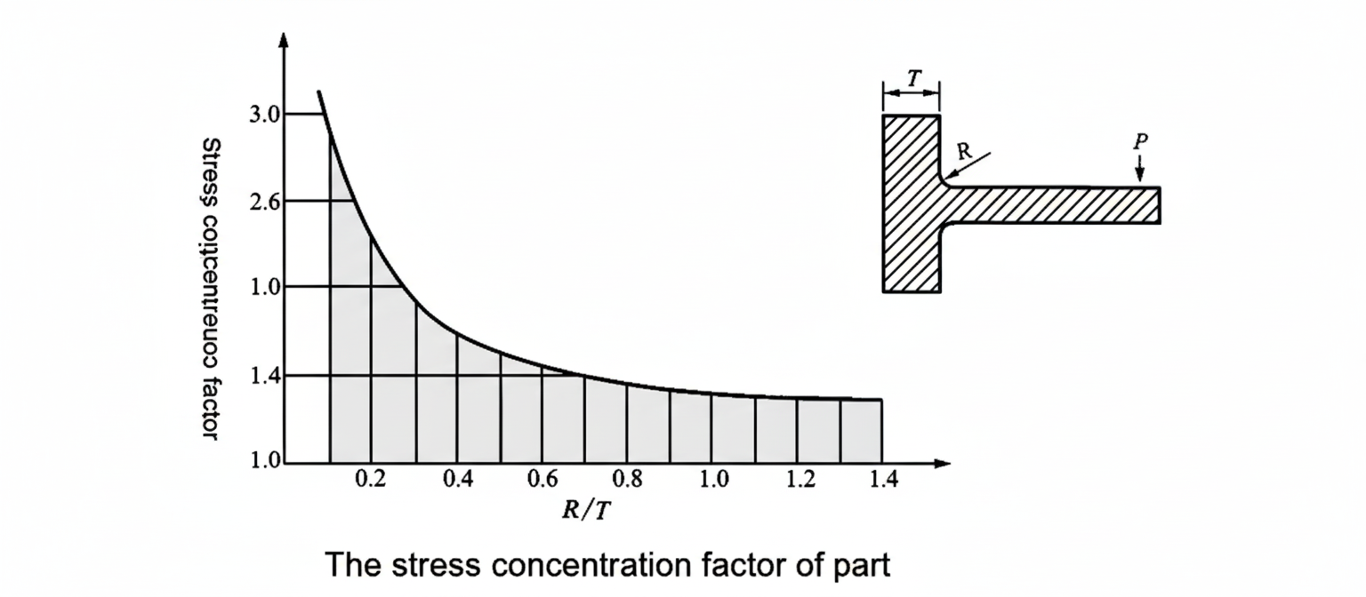
The green part (binder + powder) shrinks by 15–22% linearly during sintering. If wall thicknesses vary significantly, different regions shrink at different rates, leading to warpage, distortion, or cracking. Keep wall thickness between 0.5 mm and 6 mm, and transition gradually between thick and thin sections.
Gate Location Matters More Than You Think
The gate through which the feedstock enters the cavity determines flow patterns in the green state and shrinkage behavior during sintering. Gating should be placed at the thickest section to ensure uniform cavity fill and to minimize weld lines. Multiple gates may be needed for complex geometries, but each gate introduces potential knit-line weakness.
Sintering Support Is Critical
During sintering, the part softens and can sag or distort under its own weight. Design features such as flat reference surfaces or symmetrical shapes make it easier to support the part on setters in the furnace. Avoid long unsupported cantilevers and thin, tall features that will slump.
Minimum Feature Size
Small holes, slots, and grooves must account for the fact that tooling features (cores) must be robust enough to survive the injection pressure. A general guideline is that hole diameters should be at least 0.3 mm, and depth-to-diameter ratios should not exceed 4:1 for blind holes.
Die Casting Design Pitfalls
Porosity Management Dictates the Design
Gas porosity is inherent in conventional die casting because air is trapped as the molten metal fills the cavity at high speed. Design around this by placing thick sections, cores, and machined surfaces where porosity is least critical. Avoid deep blind pockets that prevent air from escaping through vents.
Draft Angles Are Mandatory
Unlike MIM, where the binder lubricates ejection, die cast parts require draft angles of 1–3° on side walls to release from the die. Without sufficient draft, parts stick, ejector pins damage surfaces, and die life plummets. Internal walls typically need 2–5° of draft depending on depth.
Wall Thickness and Solidification
Thin walls (down to 0.5 mm for zinc, 1.0 mm for aluminum) are achievable in die casting, but abrupt transitions from thin to thick sections create hot spots that cause shrinkage porosity. Maintain gradual transitions and use ribs for stiffness rather than locally increasing wall thickness.
Undercuts Add Significant Cost
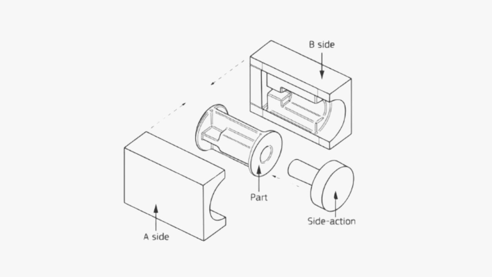
Undercuts in die casting require side cores or slides in the die, increasing tooling cost and cycle time. Whenever possible, design the part so that all features are oriented parallel to the die opening direction. Complex undercuts that require multi-slide dies can double or triple the tooling investment.
Cost Structure: Where the Money Goes
Cost modeling for MIM and die casting requires looking at the full production chain, not just the per-shot cost. Each process has a very different expense profile.
Tooling Investment
MIM tooling is typically less complex than die casting tooling because the injection pressure and temperature are lower, allowing the use of less expensive mold steels and simpler cooling channel layouts. A single-cavity MIM mold for a small part might cost $15,000–$30,000. A comparable die casting die for an aluminum part of the same complexity might run $30,000–$80,000, and multi-slide or large dies can exceed $150,000.
Material Cost
MIM feedstock (powder + binder) is significantly more expensive per kilogram than die casting ingot. Fine metal powders require atomization, classification, and blending, leading to feedstock costs of $30–$100/kg for stainless steels. Die casting alloys like A380 aluminum cost $2–$5/kg. However, MIM produces near-net shapes with almost no material waste, while die casting generates scrap from runners, overflows, and trim that can be remelted and reused at a 5–10% loss rate.
Production Volume and Per-Part Cost
At low volumes (< 10,000 parts), both processes are dominated by tooling amortization. MIM's tooling is generally cheaper, giving it an edge for small to medium runs. At high volumes (100,000+), die casting's fast cycle times and lower material cost drive per-part pricing well below MIM. The breakeven point varies by part geometry, but MIM typically becomes less competitive above 200,000–500,000 units unless the material requirement forces MIM.
Secondary Operations
MIM parts rarely need secondary machining because the sintered dimensions are predictable and the surface finish is good. Die cast parts frequently require trimming, deburring, and sometimes CNC machining of critical surfaces, adding 10–40% to the per-part cost depending on tolerance requirements.
Heat Treatment and Finishing
MIM parts often require sintering, debinding, and optionally heat treatment (solution treatment, aging, nitriding, etc.), adding to both cost and lead time. Die cast parts may need surface treatments such as chromate conversion, powder coating, or painting for corrosion protection, particularly for zinc and magnesium alloys.
How to Choose Between MIM and Die Casting
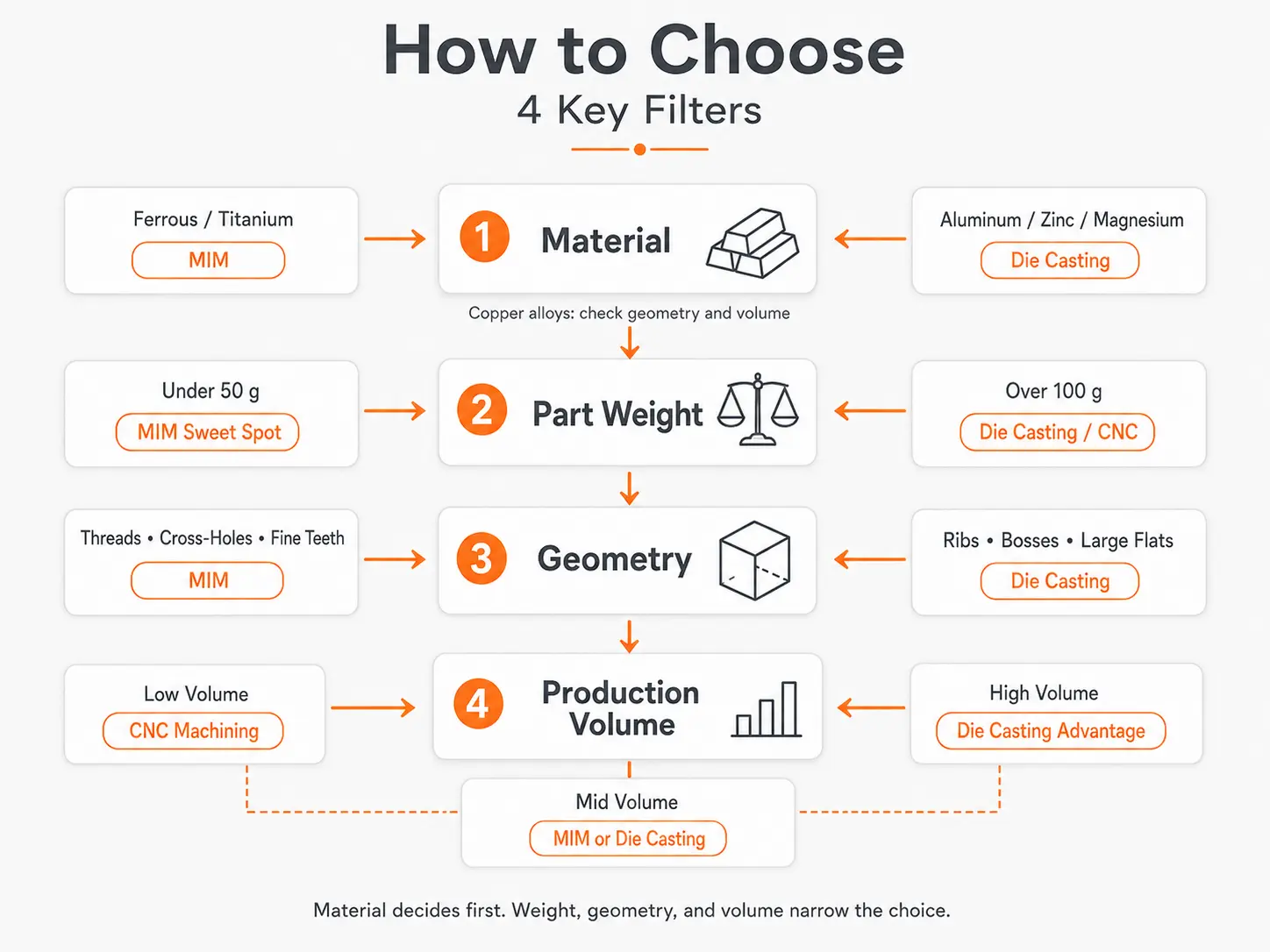
The decision framework reduces to four primary questions:
1. What material does the application require?
If the part must be made from stainless steel, titanium, tool steel, nickel superalloy, or a soft magnetic alloy, MIM is the only practical high-volume option. If the requirement can be met by aluminum, zinc, or magnesium alloys, die casting becomes viable.
2. How large is the part?
MIM is inherently limited to small parts—typically under 100 grams, though parts up to 1 kg are possible with special processing. Die casting readily handles parts from a few grams to over 20 kg. For parts larger than a fist, die casting is almost always the better choice.
3. What are the mechanical requirements?
Parts requiring high strength, fatigue resistance, or pressure tightness favor MIM's near-full density. Die casting is sufficient for housings, covers, brackets, and decorative components where some porosity is acceptable.
4. What is the annual volume?
Below 50,000 parts per year, MIM's lower tooling cost and reduced secondary operations often produce a lower total cost. Above 200,000 parts per year, die casting's fast cycle time and cheap raw material typically win on per-part cost, provided the material and size constraints are met.
Quick Reference: When to Choose Each Process
| Factor | Choose MIM When | Choose Die Casting When |
| Material | Stainless steel, titanium, tool steel, superalloys | Aluminum, zinc, magnesium, copper alloys |
| Part Weight | < 100 g (typical); up to 1 kg (special) | Few grams to 25+ kg |
| Complexity | Very high—internal threads, thin walls, intricate 3D features | Moderate to high—undercuts add cost |
| Mechanical Strength | Near-wrought properties needed; fatigue or pressure loads | Moderate strength acceptable |
| Annual Volume | 10,000–200,000 units (typical sweet spot) | 50,000–1,000,000+ units |
| Surface Finish | Good as-sintered; can be polished or coated | Good as-cast; coating often required for corrosion |
| Lead Time (first article) | 10–16 weeks (tooling + sintering development) | 8–14 weeks (die design + tryout) |
Conclusion
Metal Injection Molding and Die Casting are not direct competitors in most situations. They serve overlapping but distinct segments of the high-volume metal parts market. MIM excels when the material must be stainless steel or an exotic alloy, the part is small and intricate, and near-wrought mechanical properties are essential. Die Casting dominates when the part is larger, made from aluminum or zinc, and cost per unit at high volume is the overriding concern.
At SHBD Metal, we support both manufacturing pathways and can guide you through the trade-offs. Our engineering team evaluates material requirements, dimensional targets, production volumes, and budget constraints to recommend the process that fits your project. Whether you need MIM for precision surgical instrument components or die casting for automotive housings, we have the capability to deliver.
Contact us at Carina@shbdmetal.com or call +86 182 97910985 to discuss your next metal forming project.
Frequently Asked Questions
Q: Can MIM replace die casting for aluminum parts?
Technically yes, but it is rarely economical. Aluminum MIM feedstock is expensive relative to casting ingot, and the sintering cycle adds time. Die casting produces aluminum parts faster and cheaper. MIM of aluminum is reserved for applications requiring very thin walls (< 0.5 mm) or complex internal features that cannot be die cast.
Q: Is die casting suitable for small, intricate parts?
It depends. Zinc die casting can produce quite detailed geometries with thin walls and small features due to the low melting temperature and good fluidity. Aluminum die casting is less capable in this regard because the higher melting point and faster solidification limit flow into thin sections. For very small, highly detailed parts, MIM generally produces better results.
Q: Which process delivers tighter tolerances?
Both can achieve similar as-formed tolerances (±0.1–0.3 mm), but the mechanisms differ. MIM tolerances are affected by predictable sintering shrinkage that can be compensated in the mold design. Die casting tolerances depend on die wear, alloy solidification behavior, and seasonal variations. After sintering, MIM tolerances are highly stable. Die cast parts may require secondary machining to achieve tight tolerances on critical surfaces.
Q: How long does a MIM sintering cycle take?
A typical batch sintering cycle for stainless steel MIM parts runs 8–16 hours, including ramp-up, soak at temperature (1300–1400 °C), and controlled cooling. Thermal debinding may add another 4–8 hours. This is why MIM is a batch process, not a continuous one, and why tooling cost savings must be balanced against longer overall lead times.
Q: What are the main defects in each process?
In MIM, the most common defects are cracking (from differential shrinkage), distortion (from uneven support during sintering), and voids (from incomplete binder removal). In die casting, porosity (trapped gas), cold shuts (incomplete fusion of metal fronts), and flash (metal escaping the die) are the primary quality issues.
Q: Can a part be switched from one process to the other mid-production?
Not easily. The material, tooling, design features, and dimensional targets are all optimized for one process. Switching typically requires a complete redesign, new tooling, and requalification. It is far better to choose the right process at the design stage than to attempt a late-stage conversion.