

A Profile Is a Cross-Section, Not a Process
A profile is a length of aluminum whose cross-section is identical at every point from one end to the other. That is the whole property, and it is what makes profiles useful: every metre behaves the same way, so jigs, fasteners, seals and load calculations repeat along the part instead of being re-derived at each station.
It is also the hard limit. The section cannot taper, step, or grow a boss somewhere along its length, so anything that varies has to be machined in afterwards or joined on. Extruded aluminum is a material form; a profile is an engineered section. Confusing the two is how sections get chosen from a catalog by appearance and then fail on fit — a T-nut that will not seat, a frame that deflects under the load it was meant to carry, a dimension the die never could hold. All three are cross-section decisions, and all three are still changeable on the drawing.
Solid, Hollow, Semi-Hollow: Three Classes
Profiles are sorted into three classes by what the cross-section does with a void, and the class decides the die. Since the die decides tooling cost, lead time and first-article risk, the class is the first choice on the drawing rather than a description of it.
| Class | Cross-section | Die and risk | Watch for | Typical parts |
|---|---|---|---|---|
| Solid | No enclosed void | Flat die; lowest tooling cost and risk | Nothing structural — the limits are the load | Brackets, angles, flat bar, structural beams, heat-sink bases |
| Hollow | One or more fully enclosed voids | Porthole or bridge die; mandrel and a longitudinal weld line | Weld line against bending, anodizing or pressure duty | Tube, frame sections, enclosures, multi-void window and door profiles |
| Semi-hollow | Void partially enclosed by a gap | Tongue die; tongue deflection caps the geometry | Deep, narrow cavities; screen with the gap ratio | C-channel, snap-fit housings, trim with a narrow mouth |
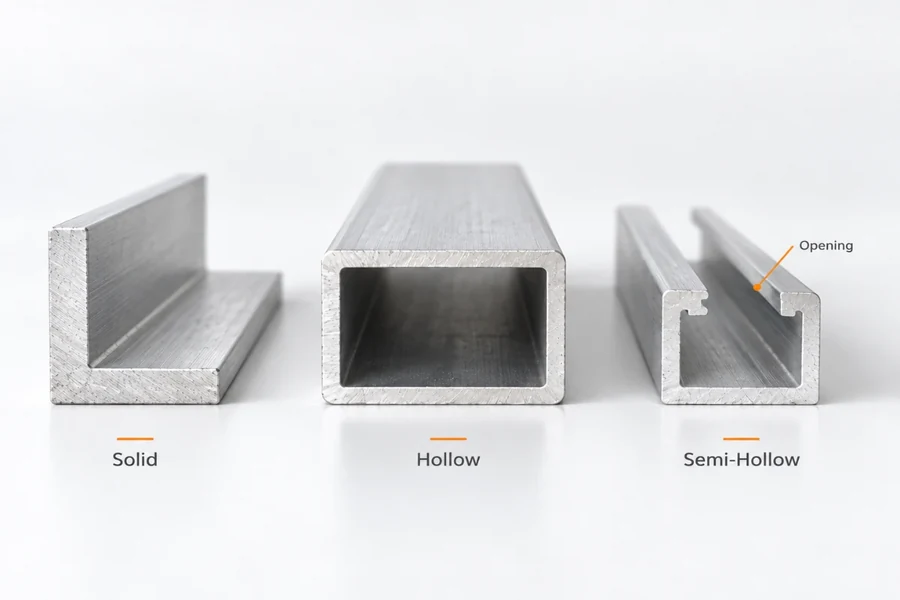
The three classes on the same bench: no void at all, a fully enclosed void, and a void partially closed by a narrow mouth — each one a different die.
Solid sections — bar, rod, flat bar, angle, channel, beam — carry no enclosed void and run through a flat die: a plate with the section cut through it. It is the simplest tooling in the process, and the right answer whenever the load path is direct and no enclosed volume is needed for cabling, fasteners or a thermal path.
Hollow sections have one or more fully enclosed voids, which means the die needs a mandrel, and the metal has to split around it and weld back together before it exits. That leaves a longitudinal weld line running the length of the part, and the line matters if the profile will be bent, anodized or pressure loaded. Two voids are harder than one, and a section that can be rearranged into a single balanced void often drops a class — which is tooling cost falling out of a drawing change.
Semi-hollow sections partially enclose a void, and the void is formed by a cantilevered tongue in the die. Tongue deflection and breakage are what limit the geometry here, so the screen is the gap ratio: the area of the partially enclosed void divided by the square of the gap width that opens it to the outside. Published thresholds sit in the region of 2.0 to 4.0 and move with the gap width, with whether the void is symmetrical about the gap centreline, and with the alloy series and standard system involved. Screen with the ratio, then confirm against the extruder's own table.
What Each Shape Buys and What It Costs
Shape is where the money starts moving. Every family here trades die complexity, perimeter or downstream work for one specific behaviour.
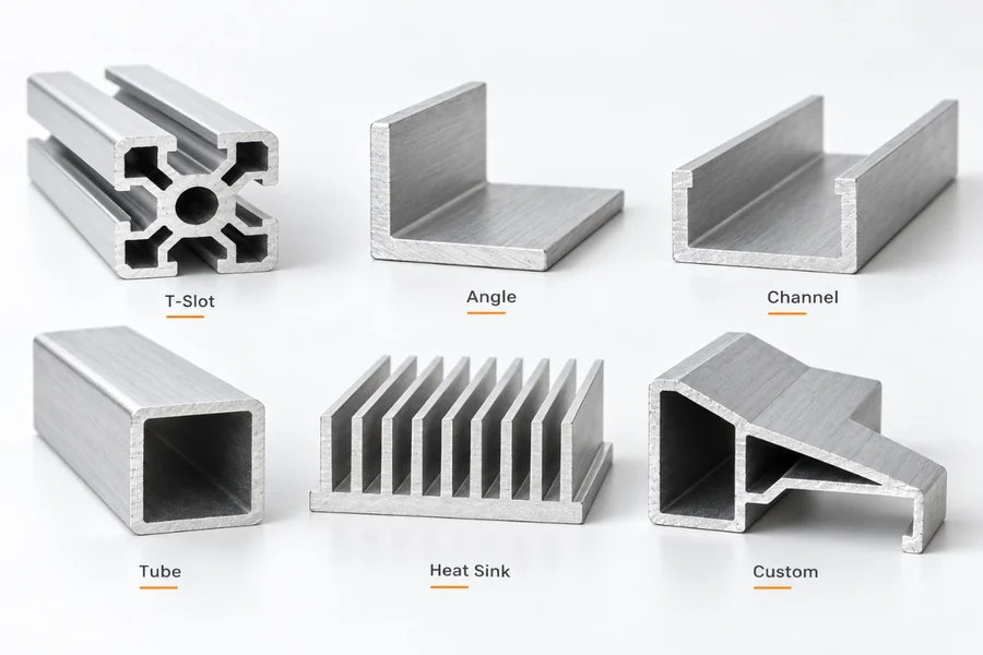
The shapes that cover most profile work. T-slot and channel frames take hardware; tube and closed sections take torsion; fin arrays and asymmetric sections cost a die.
- T-slot sections carry continuous T-grooves that take T-nuts and brackets, which is why they own modular framing. Every slot adds perimeter, and perimeter drives both die cost and extrusion pressure, so it is worth paying only for the slots the build will actually use.
- Angles come as equal or unequal L legs and suit brackets, gussets and edge protection. They are the cheapest section to make and the weakest under torsion.
- Channels in U and C form serve as tracks, guides and panel edges. Push the mouth narrow enough and it stops being a channel: the section becomes semi-hollow, with the tongue die and the class change that implies.
- Round and square tube carry more torsional stiffness per kilogram than any open section, which is why frames and rails are built from it. At equal wall thickness, a round tube is also the easier of the two to extrude.
- I, H and Z sections push metal out to the flanges where bending stress lives: efficient on one axis and weak on the other, so fix the load direction before choosing one.
- Heat-sink sections are fin arrays, and fin height against fin gap is the same tongue problem a semi-hollow section has. Finishing and anodizing have their own limits on how fine that array can be.
- Custom asymmetric sections put metal only where the load path, the thermal path or the assembly actually needs it. What you buy is consolidation; what you pay for it is a die.
On framing systems, T-slot series describes the slot width, and the hardware seats in the slot — so T-nuts, brackets and fasteners have to match the series of the profile they go into. Mixing series inside one build multiplies part numbers and produces assembly mismatches between pieces that look identical on a drawing. Metric framing families commonly run from 10 mm to 160 mm across the face, and the slot is what has to match, not the outer size alone.
Standard Sections or a Custom Die
A standard profile comes off a die that already exists, so its geometry is fixed by the catalog and there is no tooling to pay for. A custom profile gets a die cut to your section, which buys geometry the catalog cannot provide and charges for it up front.
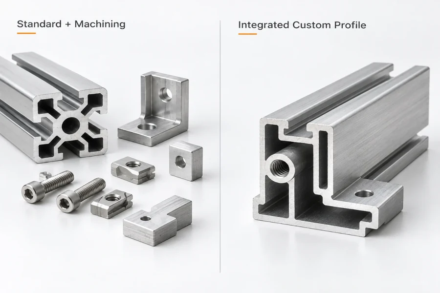
The trade in one picture: a catalog section plus the parts machined onto it, against a custom section that extrudes the bosses, channels and mating faces into the die.
| Factor | Standard profile | Custom profile |
|---|---|---|
| Tooling | Existing die, no tooling charge | New die cut to your section |
| Design freedom | Fixed by the catalog | Section shaped around load, assembly and thermal path |
| Lead time | Shortest, from stock or near-stock | Die manufacture plus a first-article run |
| Minimum volume | Single lengths | Tooling spread across the run; small batches possible with more tooling in the unit price |
| Secondary machining | You machine to fit | Machining features designed into the section |
| Best fit | Framing, guarding, general structure | Consolidated parts, proprietary geometry, thermal or sealing function |
There is no universal minimum order or die price, because both depend entirely on the section. What can be judged from the drawing is whether a custom die is worth cutting:
- No standard section provides the geometry the part needs.
- Two or more components can be consolidated into one cross-section.
- Machining operations or fastener count drop far enough to pay the tooling back.
- Projected volume spreads the tooling cost across enough parts.
- Weight, stiffness or thermal performance is a requirement rather than a preference.
That last point is the one that separates a custom profile from an expensive piece of standard stock. When the geometry is doing real work, custom extrusion is the right conversation to have; when it is filling a gap in a frame, the catalog wins.
Alloy and Temper Decide Strength and Finish
The alloy sets the ceiling on strength, surface and corrosion behaviour, and the temper sets where inside that ceiling the part actually sits. Four alloys cover most profile work.
| Alloy and temper | Tensile / yield | Extrudability | Surface | Typical profile use |
|---|---|---|---|---|
| 6063-T5 | 152 / 110 MPa | Excellent | Best as-extruded, anodizes evenly | Visible trim, architectural sections, enclosures, heat-sink fins |
| 6063-T6 | 207 / 172 MPa | Excellent | Best as-extruded, anodizes evenly | Trim and enclosures needing more strength than T5 |
| 6061-T6 | 262 / 241 MPa | Good | Good; shows die and weld lines more readily | Structural frames, machine components, automotive |
| 6005A-T61 | 262 / 241 MPa | Good | Good | Thicker structural sections, transport and rail |
| 1100 | Low (non-heat-treatable) | Excellent | Good, excellent corrosion resistance | Chemical equipment, electrical parts, food-handling gear |
Read the table as a set of trades. 6063 gives the best as-extruded surface and anodizes evenly, which is why visible trim, architectural sections and heat-sink fins use it. 6061 is the structural choice and the one that shows die lines and weld lines most readily, so where a part both carries load and is seen, the finish is specified to suit rather than the alloy being compromised. 6005A covers the thicker structural sections in transport work, and 1100 covers the applications where corrosion and conductivity matter more than strength.
Two habits remove most of the arguments later: state the temper with the alloy, because 6063-T5 and 6063-T6 are different materials on a drawing, and check the weld line's position against any bending, anodizing or pressure duty the part will see. Our own aluminum alloy guide covers the wider family beyond extrusion.
Design Rules the Die Will Enforce
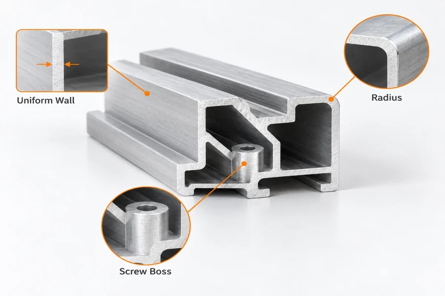
Uniform wall, a radius where two walls meet and a screw boss planned into the section. All three are cheap in CAD and expensive to add after the die is cut.
- Keep wall thickness reasonably uniform. Walls of very different thickness cool at different rates, and the differential drags the section out of dimension. Adjacent wall ratios above about 2:1 are worth avoiding, and where two walls of different thickness meet, a radius belongs at the junction.
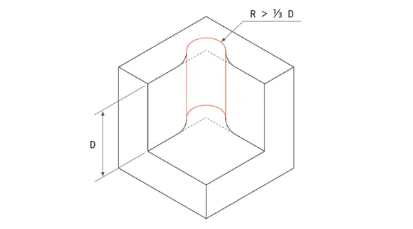
- Use generous radii. A sharp corner is hard for metal to fill, concentrates stress, and leaves a knife edge on the die itself that wears or chips away.
- Keep cavities shallow and wide relative to their mouth. This is the tongue problem once more, and it is the failure that shows up most often on a custom die.
- Favour symmetry where the function allows it. A balanced section fills and cools evenly, and that shows up as tighter dimensional control from part to part.
- Put machining allowance only on surfaces that will actually be cut. Every machined face is a cost line, so the allowance belongs on the faces that mate and nowhere else.
- Plan screw bosses, cable channels and joining features into the section. Extruding them is far cheaper than adding them later, and a boss too thin to tap is a redesign rather than a tolerance problem.
As a working range, custom sections sit around 1.0 to 2.5 mm wall, with 2 mm or more where the part carries load. The section that ignores this rule does not fail at the die; it fails three weeks later, when the first article comes off the line with a twist in it.
Tolerances, and the Machining After Them
Extrusion tolerances are a set of parameters rather than a single number, which is why they are specified by parameter on the drawing:
- Dimensional — cross-section dimensions, wall thickness, cut length.
- Straightness — deviation along the length.
- Twist — rotation about the longitudinal axis.
- Flatness — deviation across a face.
- Angularity — the angle between two surfaces that meet.
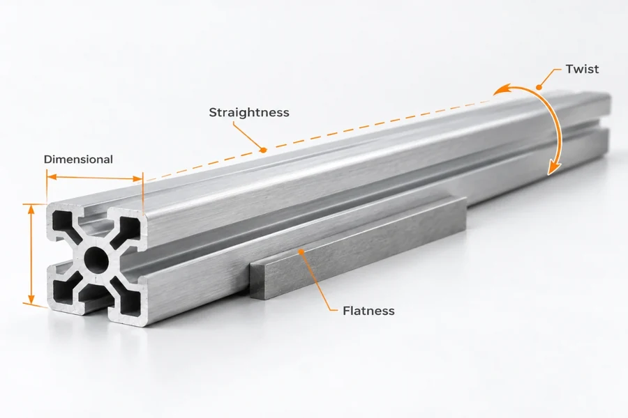
Extrusion tolerances are specified by parameter, not as one number: dimensions across the section, straightness along the length, twist about the axis and flatness across a face.
The Aluminum Association tables in Aluminum Standards and Data are the usual default, split into standard and precision classes, and they cover most work. Restrict the tight values to dimensions that mate with something else. Precision tooling and added inspection are both paid for, and neither improves a face that contacts nothing.
When the drawing asks for something tighter than the press can hold, the route is a second operation: cut the face, bore the hole, then measure it. That turns the tolerance question into a machining question, which is a better trade than trying to buy precision out of a press. Mark which dimensions are critical on the drawing instead of applying a blanket tolerance across the section — see the tolerances we work to.
Extrusion delivers the section; the finishing decides the part. Milled ends, pockets, slots and true mating faces come off a machining centre; drilling and tapping add the threads a die cannot produce; sections are cut to length, mitred or notched, then welded into frames and sub-assemblies. Anodizing adds a hard oxide layer but amplifies surface variation rather than hiding it, powder coating hides more with a thicker film, and bead blasting gives a uniform matte texture before either. Treat the whole chain as one package: a profile designed to be machined, finished and inspected in one flow costs less than the same profile re-handled between shops.
Where Profiles Are Used
Application narrows the choice faster than alloy or finish does, because each field loads a profile differently.
| Application | Section that fits | Why |
|---|---|---|
| Industrial automation framing | T-slot square and rectangular | Slot takes hardware without welding |
| Machine frames and guarding | Hollow tube and T-slot | Closed section resists torsion |
| Electronics enclosures | Custom hollow with screw bosses | Bosses and guides come out of the die |
| Heat sinks | Fin arrays in 6063 | Fine fins extrude and anodize evenly |
| Automotive and transport | Hollow multi-void in 6005A | Structure against a weight target |
| Robotics | Lightweight hollow and T-slot | Stiffness per kilogram |
| Medical and laboratory equipment | Smooth 6063 and custom sections | Cleanable surfaces, integrated cable paths |
| Consumer products | Custom asymmetric | Cosmetic face and structure in one part |
Read the pattern rather than the table: closed sections appear wherever torsion or stiffness per kilogram matters, slots appear wherever the frame has to come apart or be adjusted, and custom sections appear where a boss, a cable path or a cosmetic face has to come out of the die instead of a machining operation.
Extruding the Section, Machining the Part
Extruded profiles reach us as stock and leave as finished parts. The work that decides the tolerances on most profile jobs is the second operation: milled ends and pockets, slots, drilled and tapped holes, and true mating faces cut on CNC machining centres, then cut to length, mitred or notched as the assembly needs. Because the section has to be planned around what will be machined afterwards, the profile and the machining are quoted as one job — see aluminum extrusion for the extrusion side and custom extrusion when the cross-section is being designed for a specific part.
A clean RFQ gets a clean quote. Send the CAD model plus a dimensioned cross-section drawing, alloy and temper, the critical dimensions with the tolerance for each, cut length and quantity, surface finish, secondary machining requirements, inspection requirements, and the prototype and production quantities separately. Our quality system is ISO 9001:2015; where a programme requires IATF 16949 or ISO 13485, say so at the RFQ stage and we will confirm whether the route fits rather than implying a certificate we do not hold. Start with the quote form, or read how the extrusion process works first.
FAQs
What exactly makes something an aluminum extrusion profile?
The cross-section is the whole definition: a length of aluminum whose section is identical at every point from one end to the other. That constancy is the useful property, because every metre behaves the same way, so jigs, fasteners, seals and load calculations all repeat along the part. It is also the hard limit. The section cannot taper, step or grow a boss somewhere along its length, so any feature that varies has to be machined in afterwards or joined on.
What is the difference between solid, hollow and semi-hollow profiles?
The classes are sorted by what the cross-section does with a void, and the class decides the die. A solid section has no enclosed void anywhere and runs through a flat die, the simplest and cheapest tooling in the process. A hollow section has one or more fully enclosed voids and needs a porthole or bridge die, where the metal splits around a mandrel and welds back together before it exits. A semi-hollow partially encloses a void — a narrowed channel mouth, for instance — and the void is formed by a cantilevered tongue in the die, whose deflection limits how far the geometry can be pushed.
How do I know whether my section is semi-hollow?
Screen it with the gap ratio, the area of the partially enclosed void divided by the square of the gap width that opens it to the outside. Suppliers publish thresholds in the region of 2.0 to 4.0, varying with the gap width and with whether the void is symmetric about the gap centreline, and they shift again with alloy series and with the standard system an extruder works to. Use the ratio to screen, then confirm the section against the extruder's own table rather than trusting the calculation alone.
Which aluminum alloy should a profile use?
Four alloys cover most profile work, and the choice is usually surface against strength. 6063 gives the best as-extruded surface and anodizes evenly, so it is the default for visible trim, architectural sections and heat-sink fins. 6061 is stronger and is the structural choice — frames, machine components, automotive — but it shows die lines and weld lines more readily. 6005A sits with it for thicker structural sections in transport and rail work. 1100 is weak but corrodes very well and suits chemical, electrical and food-handling parts. State alloy and temper together, because 6063-T5 and 6063-T6 are not the same material on a drawing.
What wall thickness should a custom profile use?
Keep walls as uniform as the function allows, and avoid adjacent walls differing by more than about 2:1, because walls of different thickness cool at different rates and pull the section out of dimension. Where two walls of different thickness meet, put a radius there rather than a step. On a custom section, walls in the region of 1.0 to 2.5 mm cover most work, and anything that carries load is usually 2 mm or more. Thin walls extrude faster but leave little room for a thread or a machined face.
What tolerances can an extrusion hold?
Extrusion tolerances are a set of parameters rather than one number: cross-section dimensions, wall thickness and cut length; straightness along the length; twist about the longitudinal axis; flatness across a face; and angularity where two surfaces meet. The Aluminum Association tables in Aluminum Standards and Data are the usual default on a drawing, split into standard and precision classes. Standard tolerances cover most work, and it is worth tightening only the dimensions that mate with something else, because precision tooling and extra inspection cost money without improving a surface nothing touches.
Can an extruded profile be machined afterwards?
Yes, and on most parts it has to be. Extrusion sets the cross-section and the length; machining adds what a die cannot produce — trimmed ends, pockets, slots, mounting holes, threads and true mating faces. It is also the route to a tolerance tighter than extrusion can hold: mill the face, bore the hole, then inspect it. Leave allowance on any surface that will be cut, and mark the critical dimensions on the drawing instead of applying a blanket tolerance across the whole section.
When is a custom die worth cutting?
When the section is doing real work rather than filling a catalog gap. The pattern that justifies one is repeatable: no standard section provides the geometry the part needs, two or more components can be consolidated into a single cross-section, machining operations or fastener count drop far enough to pay the tooling back, or weight, stiffness or thermal performance is a requirement rather than a preference. Standard sections remain the better answer for framing, guarding and general structure, where the catalog already has the shape.
Summary
The profile decision runs in one direction, and it is worth running in order: the load fixes the geometry, the geometry fixes the class, the class fixes the die, and the die plus the tolerances set the cost. Solid sections keep the flat die and the lowest tooling risk; hollow and semi-hollow sections buy enclosed volume and internal features, and pay for it in mandrels, tongues and a longitudinal weld line that has to be kept away from bending, anodizing and pressure duty.
Standard sections cover framing, guarding and general structure. Where the cross-section has real work to do — consolidating parts, carrying load, routing cable or shedding heat — a custom die earns its tooling back. Either way, what the drawing should say is the alloy and temper, the wall thickness and 2:1 ratio, the tolerance by parameter, and which faces will be machined afterwards. If you have a section in mind, send it over and we will say which class it falls into and what it will take to hold it.
Comment
0 comments
Got thoughts or experiences to share? We’d love to hear from you!