
Where Large Format Starts
The term has no official cutoff, which is why it gets applied to everything from a 400 mm bracket to a three-metre tool. In practice it starts to mean something once the part passes roughly half a metre on its longest axis, and the top of the range reaches a couple of metres on gantry and robotic extrusion systems.
Machine envelopes are a weak anchor here, because two machines both described as large format can differ by a metre. The part's longest dimension is the honest number, and it also predicts what the part has to survive: something at 600 mm still behaves like a scaled-up small part, while something at three metres has to hold its own weight and cool without distorting itself.
Which Process Takes Which Size
Large scale printing is not one process. The route a part lands on is decided first by its longest dimension, then by whether it has to carry load.
| Process | Typical largest part | Layer height | Best fit |
|---|---|---|---|
| Pellet extrusion (granule feed) | up to about 1.5 × 1.5 × 2 m on the largest gantry systems | 0.5–3 mm | large tooling, jigs, structural parts |
| Large-format FDM (filament) | around 1 m on the longest axis | typically 0.2–0.5 mm | prototypes, fixtures, durable end-use parts |
| Industrial resin (SLA/DLP) | around 0.8 m, up to about 1.4 m on the largest vats | typically 0.05–0.2 mm | smooth master patterns, detailed models |
| SLS / MJF (polymer powder) | around 0.4–0.7 m | typically 0.08–0.12 mm | functional parts with no support removal |
| SLM (metal powder) | around 0.3–0.5 m | typically 0.03–0.06 mm | dense metal parts inside a sealed chamber |
Treat those envelopes as the design ceiling rather than a target, because the machine specification is the easy part of the decision and it is not the one that usually decides the outcome. What matters more is whether the geometry can be printed in a direction that keeps layers out of the load path.
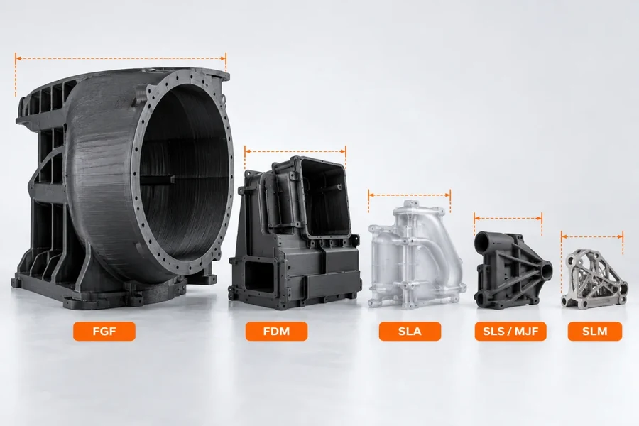
The same nominal part across the processes: envelope shrinks by roughly an order of magnitude from pellet extrusion to metal powder melting, and so does the layer height.
Polymer routes. Pellet extrusion is the only polymer process that genuinely prints parts this large. It feeds granules rather than filament and melts them far faster, so material goes down at a rate a filament head cannot match — which is also why it is the cheaper route per kilogram. Filament FDM sits below it at around a metre, and it is the one to pick when the part needs finer detail than a pellet head can hold. Industrial resin printing trades strength for surface quality and is the right route for a smooth master pattern.
Powder-bed routes. SLS and MJF have no support structure to remove, so internal channels and lattice geometry come out clean, and the size ceiling that comes with the process is the price. Metal powder melting does the same thing for metal, but only inside a sealed chamber — and that chamber is what keeps the metal envelope so much smaller than the polymer one.
One Piece, or Sectioned and Joined
The envelope decides whether the part can print in one piece. It does not decide whether it should.
Printing whole is the cheaper route whenever the part fits: no joint to design, no alignment step, no seam to hide or finish. Sectioning buys the size back and charges for it — but it also frees the machine sooner, since one large build can occupy a printer for days, and every cut adds a joint to place, execute and finish.
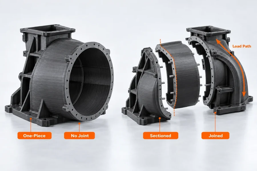
Printing whole removes the joint; sectioning buys the size back and adds a joint to place, execute and finish — which is why the cut belongs away from the load path.
The parting plane and the build orientation are settled together, because the orientation that keeps layers out of the load is not always the one that splits cleanly. Once the joint location is fixed, the method comes down to load and service:
| Method | Strength | Typical use | Limitation |
|---|---|---|---|
| Structural adhesive | moderate to high | the default for most large parts | needs a flat, clean face and cure time |
| Mechanical fasteners | highest | parts that have to come apart | needs bosses or embedded inserts |
| Welding | moderate | same-material joints away from visible faces | heat distorts the material around the seam |
Where the cut lands matters more than how the pieces are held: keep the cut plane out of the load path, and hide the seam on a face nobody looks at. Then the part gets finished: what leaves the printer is close to shape but not to size, because after joining, the seam and every face that locates something else are cut back — and it is that operation, not the print, that sets the tolerances on the drawing. It is worth arranging that second step when the job is quoted rather than after the sections come off the machine.
Design Rules That Only Show Up at Scale
Most printed-part design advice is written for parts where distortion is a rounding error. Push a part past a metre and that stops being true, because the geometry starts fighting the process in three specific places.
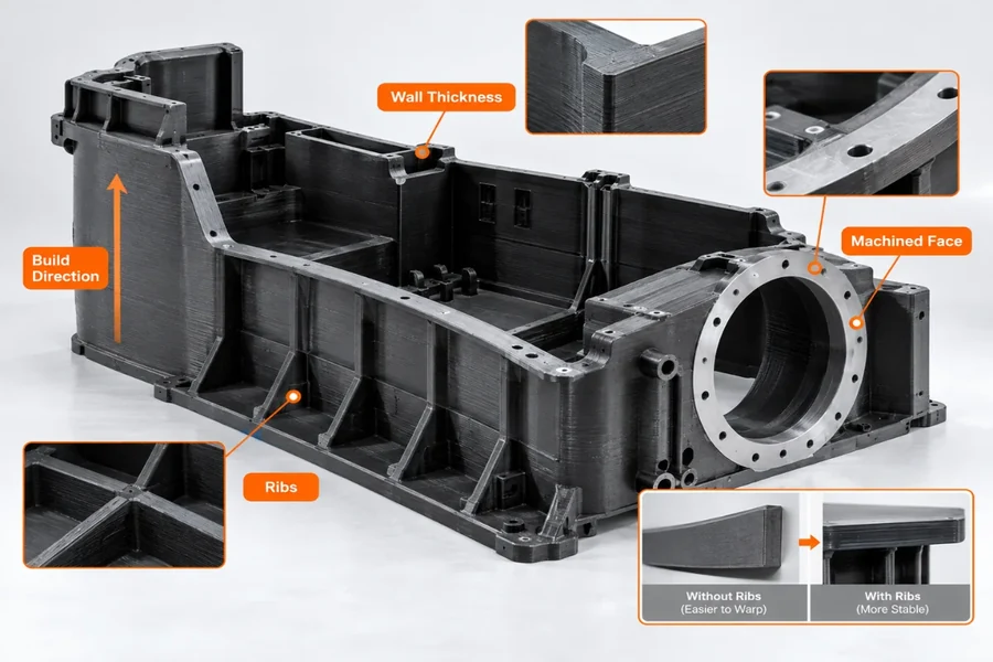
The three features that decide whether a large print stays in tolerance: build direction, ribs under a long flat face, and the faces that are machined back rather than printed.
- Long flat faces pull out of flat. The fill runs continuously and cools unevenly, so the face moves as it is built. Ribs or a ribbed pattern underneath are usually what holds it — added in CAD they cost almost nothing; added after the first print they cost a redesign.
- Wall thickness loses its fixed floor. A wall that prints cleanly at 100 mm can flex or sag over a metre, so on a large part the minimum is set by the load it carries rather than by the smallest wall the nozzle can lay down.
- Locating features are the quiet failure. Bosses, holes and mating faces have to survive print tolerance across a long build, and the error grows with the part. Where they set position, they are normally printed near net and machined back rather than trusted as printed.
Underneath all three sits one fact: a printed section is weaker between layers than along them. The practical conclusion is to fix the build direction while the geometry is still open, and to add ribs and generous fillets at the same time: in CAD both are nearly free, and retrofitting either after the first print is not. Our print tolerance guide covers how much of that error to expect on each process, and the materials guide covers what the higher-temperature grades buy you.
Where a Large Print Earns Its Place
The parts that justify a large build are usually the ones where the first article is also the last one. Layup molds, autoclave tools, welding jigs and inspection nests are the standard examples: they are large, their geometry is usually too complex to machine cheaply from a billet, and one of each is all that is needed.
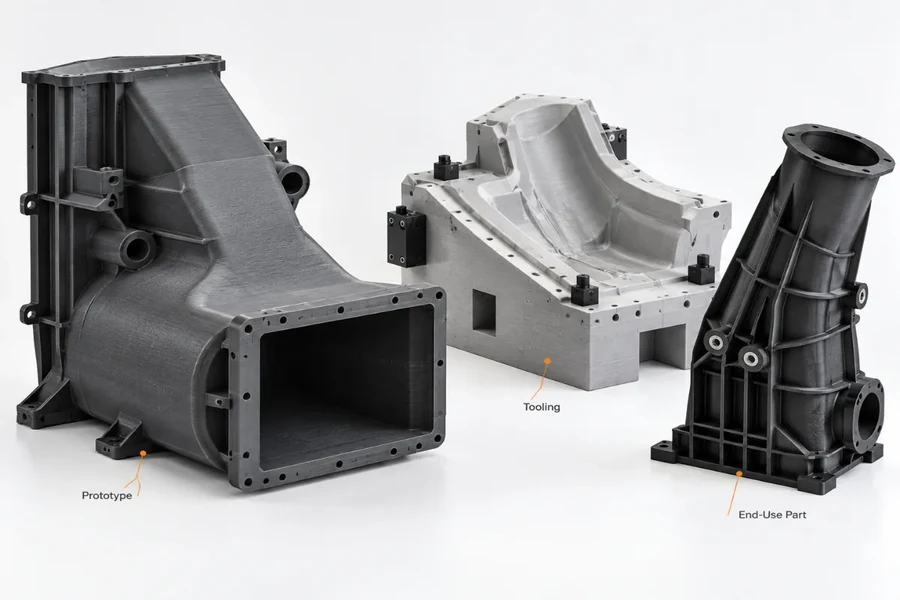
The three jobs a large build usually does: a full-scale prototype, a tool such as a layup mold or nest, and a low-volume end-use part.
Full-scale prototypes are the other clear group. A container, a panel or a housing tested at reduced scale says very little about stiffness, fit or airflow, so if the question is how the real thing behaves, the prototype has to be the real size. Low-volume end-use parts follow the same logic: large flat faces, internal channels, long spans and integrated mounting points are exactly the features that make a part worth printing instead of fabricating, and exactly the ones that would be slow and wasteful to machine from solid.
What Drives the Quote and the Schedule
Cost on a large print is dominated by time rather than material, which is the opposite of how most small-part pricing works. A quote usually breaks into four lines:
- The volume of material the part actually contains.
- Machine time, since a long build occupies the machine for all of it.
- Post-processing labour — support removal, sanding and sealing all scale with surface area rather than with part count.
- Whether the print has to be cut into sections and joined afterwards — a second operation standing on top of the build.
Size alone does not predict the number: an empty shell and a solid block of the same envelope can sit on the machine for comparable hours while consuming wildly different amounts of granulate. The lever worth attacking first is almost always machine time, and the second is orientation: standing a part up to suit the load also decides how tall the build is, how much support it needs and how long the machine is tied up.
The schedule answers to three things only: when a machine comes free, how long the build occupies it, and how much hand work the part needs afterwards. On a build that runs for days the queue matters as much as the print — which is the practical argument for splitting a part that is only slightly too large for the envelope.
Against Machining, Molding and Sheet Metal
Printing comes out ahead when the part is one of a few, the geometry is complex, and the design is still moving. Complexity matters more than size.
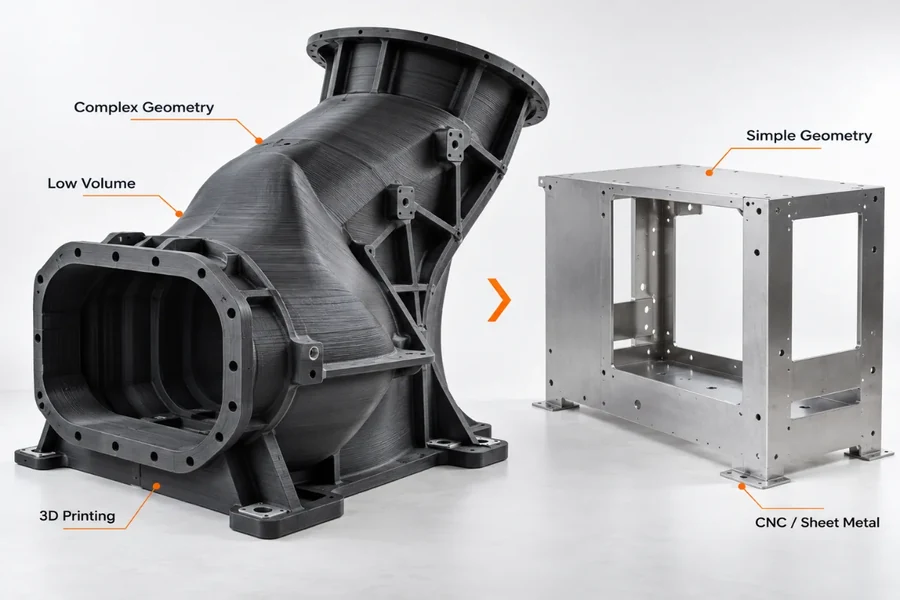
The comparison that matters most: complex geometry at low volume belongs on a printer; a simple frame belongs on a machine or in sheet metal.
- Against CNC machining: printing wins on complex geometry and low counts, and loses once the part is simple enough to cut from plate or billet. Machining also sets tolerances a print cannot, which is why the two are often used on the same part.
- Against molding and casting: printing wins at low volume because there is no mold to pay for, and loses as quantity grows, since a mold spread across enough parts beats any print.
- Against printing small parts and assembling them: a large build removes the joints between the small parts, and on a load-bearing component those joints were the weak point.
- Against sheet metal: where the part is really a flat panel or a frame, forming it from sheet is faster and cheaper than any print, and it is worth handing that case over rather than printing it.
Large Prints and the Machining After Them
Large-format printing here runs on the extrusion routes, with the print and the finishing operation quoted as one job rather than as two: near-net geometry off the printer, then the joint faces, bolt patterns and locating features cut back to size on our machining side — see 3D printing services and CNC machining. Where the part turns out to be a flat panel or a frame after all, we will say so and quote it as sheet metal instead.
Two things we settle with you before the build starts, because both are expensive to change later: the build orientation, and where the parting plane falls if the part has to be sectioned. Send the model with the load direction and the faces that have to be accurate, and the quote can say which features come off the printer and which need a second operation. Our quality system is ISO 9001:2015; if a programme requires IATF 16949 or ISO 13485, tell us at the RFQ stage and we will say whether the route fits instead of implying a certificate we do not hold. Start with the quote form, or read how the polymer processes compare before choosing one.
FAQs
What counts as large format 3D printing?
There is no official cutoff, which is why the term gets applied to everything from a 400 mm bracket to a three-metre tool. The useful definition is a practical one: the label starts to mean something once the part passes roughly half a metre on its longest dimension, and the top of the range runs to a couple of metres on gantry and robotic extrusion systems. Anchoring the decision to the part's longest dimension works better than anchoring it to a machine envelope, because two machines quoted as “large format” can differ by a metre.
Which process should I use for a part around a metre long?
It depends on what the part has to do. Filament FDM covers roughly a metre and holds finer detail than a pellet head, so it suits fixtures, prototypes and durable end-use parts. Pellet extrusion is the route that goes past that, into the 1.5 m and larger tooling, and it lays material down far faster because it melts granules rather than filament. If the requirement is surface quality rather than size, resin printing gives the smoothest master patterns but stops around 0.8 m. If the part has to carry load and come out with no support marks, powder-bed polymer is the better route inside its 0.4–0.7 m window.
Should a large part be printed in one piece or sectioned and joined?
The envelope decides what is possible; the load path decides what is wise. Printing whole is cheaper whenever the part fits, because there is no joint to design, align or finish. When it does not fit, sectioning buys the size back and charges for it — and a joint placed in a bending member is where that member will fail first, so the cut should be kept out of the load path and put on a face that is not visible. Sectioning can also shorten the machine time on a part that is only slightly too big for the envelope.
How do you join printed sections?
Three methods carry most of it. Structural adhesive is the default for large parts and gives moderate to high strength, but it needs a flat, clean face and cure time. Mechanical fasteners give the highest strength and are the answer for anything that has to come apart, at the cost of bosses or embedded inserts. Welding suits same-material joints away from visible faces and can distort the material around the seam. Whichever is used, the joint and the critical faces are normally machined back to size afterwards, which is where the real tolerances are set.
Why does a large printed part warp?
Because the geometry starts fighting the process. On a long flat face the fill runs continuously and cools unevenly, so the face pulls out of flat while it is being built; ribs or a ribbed pattern underneath are what holds it. A wall that prints clean at 100 mm can flex or sag over a metre, so on a large part the minimum wall is set by the load rather than by what the nozzle can lay down. The underlying fact for all of it is that a printed section is weaker between layers than along them.
Can the locating features on a large part be trusted as printed?
Rarely. Bosses, holes and mating faces have to survive print tolerance across a long build, and the error accumulates with size. Where a feature sets position, the usual approach is to print it near net and machine it back, which is why a large print and its finishing operation are quoted together. The tolerances on the drawing are then set by the machining step, not by the printer.
What materials are used at this size?
Reinforced thermoplastics first: carbon- or glass-filled ABS, PC and PP cover most structural tooling, and engineering grades such as PEEK and glass-filled PPA are used where service temperature is high. Granulate also costs less per kilogram than filament does, and that pricing is one of the reasons the pellet-fed machines own the top of the size range. Metal is a separate question, because powder-bed melting works inside a sealed chamber and that chamber keeps the metal envelope far smaller than the polymer extrusion routes.
Is large format printing cheaper than machining or molding?
For one-off and low-volume parts it usually is, because there is no tooling to pay for and near-net shape wastes far less material than cutting the same form from solid. Against machining it wins on complex geometry and low counts and loses once the part is simple enough to cut from plate or billet. Against molding and casting it wins at low volume and loses as quantity grows, because a mold spread across enough parts beats any print. A large flat panel or a frame is usually cheaper as fabricated sheet metal than as a print, and that is a case worth handing over rather than printing.
Summary
The decision path is short. Start with the part's longest dimension, match it to a process, then settle whether it prints whole or gets sectioned and joined — because orientation, wall thickness and locating features only mean anything against a size and a route. Past a metre, the process stops behaving like a scaled-up small part: flat faces need ribs, wall thickness is set by load, locating features get machined back, and the layers are the weak direction. Cost is driven by machine time rather than material, which is the opposite of small-part pricing, and the lead time is decided as much by the queue as by the build.
Where the part is one of a few and the geometry is complex, printing wins over tooling. Where it is a flat panel or a frame, sheet metal wins. If you have a part in that range, send the model and we will say which route it belongs on.

Comment
0 comments
Got thoughts or experiences to share? We’d love to hear from you!