

Why Stainless Fights Back in the Press
Austenitic stainless is a poor candidate for a lazy stamping process. It work-hardens faster than the low-carbon steels most press shops are set up for, it springs back further and it galls against tool steel. None of that is a defect of the material — it is the same property set that makes 304 and 316L worth using in medical, aerospace and food equipment, where the parts have to survive cleaning, sterilisation and chloride exposure rather than just hold a shape.
The two grades are not interchangeable in the press either. 304 and 316L share the austenitic structure and the rapid work-hardening, but 316L carries molybdenum for pitting resistance and holds its non-magnetic condition better after cold work, while 304 can pick up measurable magnetic response where the forming strain is heaviest because some of the austenite transforms to martensite. That shows up in assembly, in magnetic separation and in the corrosion behaviour of the formed corner.
| Property that moves the process | 304 | 316L |
|---|---|---|
| Structure and work hardening | Austenitic, strain-hardening exponent around 0.45–0.50 | Austenitic and slightly more ductile annealed; same rapid hardening in the press |
| Magnetic response after forming | Becomes weakly magnetic at high strain (strain-induced martensite) | Stays essentially non-magnetic, which matters for instrumentation and sensors |
| Corrosion performance | PREN roughly 18–20; fine for general corrosion and cleaning | PREN roughly 23–25; the grade for chlorides, body fluids and sterilisation |
| Forming behaviour | Higher tonnage, more springback, galling risk on uncoated tools | Similar tonnage, deeper draws possible with multi-pass strategy |
| Typical stamped parts | Brackets, panels, mesh and screen frames, housings, fastener hardware | Medical device components, instrument housings, food-equipment parts, aerospace brackets |
| Post-processing | Deburring, passivation to ASTM A967 where corrosion matters | Deburring, passivation; often electropolished for cleanroom surfaces |
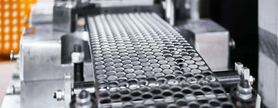
A perforated stainless panel leaving the die: the screen pattern, the formed edge and the hole quality all come from one station plan.
Springback: Over-Bend Plus Closed-Loop Control
Springback in stainless is not a surprise to be trimmed away at assembly; it is a displacement to be predicted and compensated. Two mechanisms do the work. Over-bend compensation cuts the die face so the part is formed past its final angle by roughly the amount it will recover, and servo closed-loop control adjusts the ram's bottom dead centre during the stroke so the programmed depth is actually reached on the material in the die. Together they hold the formed geometry in a ±0.01–0.03 mm band on parts that would otherwise drift by a tenth of a millimetre between coils.
The compensation value is not a constant. It depends on the material lot, the wall thickness, the radius and the direction the bend runs relative to the rolling direction, which is why the die is cut from a forming prediction and then validated on the first-off parts rather than set by feel on the try-out press.
The five problems that define a stainless stamping programme, and what controls each of them, are summarised below.
| Problem | What controls it | Parameter to watch | What it buys |
|---|---|---|---|
| Springback and dimensional drift | Over-bend compensation with servo closed-loop ram control | Formed geometry held in a ±0.01–0.03 mm band | Parts that assemble without shimming or selective fitting |
| Surface scratches and galling | Coated tool steel, polished die faces, EP lubricant, die cooling | DC53 with CVD/TD coating, die surface around Ra 0.4 µm | Decorative or cleanroom-ready surfaces straight off the press |
| Thinning and micro-cracking in 316L draws | Multi-pass draw sequence with dynamic blank-holder force | Thinning held to 15% of nominal wall | Leak-tight, crack-free drawn shells |
| Burrs on functional edges | Blanking clearance control and a planned deburring step | Clearance at 6–10% of sheet thickness per side | No assembly scratches or short circuits from a rolled edge |
| Unit cost at volume | Strip nesting and a station plan that fits one die | Material utilisation at or above 75% | The material, not the labour, stops being the cost driver |
Drawing 316L Without Cracking or Thinning
Deep drawing is where 316L punishes a single-step process. The punch pulls the wall thinner as it travels, and because the alloy hardens while it deforms, the material being stretched has less capacity left for strain than it had at the start. A part drawn in one hit either tears at the die radius or arrives with a wall that is out of specification in the middle of the shell — the classic failure being micro-cracks that pass a visual check and fail a leak or fatigue test later.
Two controls make the difference:
- Split the draw. Several lighter passes release internal stress progressively rather than in one operation, and let the material be re-lubricated and, where the specification allows, re-annealed between passes. Draw depth per pass falls, wall thinning falls with it.
- Vary the blank-holder force through the stroke. A force that starts low lets the flange flow inward; raising it as the punch descends holds the wall and stops the material feeding in faster than the shell can take it. A constant force cannot do both jobs, and this is where a controlled hydraulic or servo blank holder earns its place.
With those two in place, thinning is held to 15% of nominal wall on the drawn shell and the draw is planned for a strength coefficient in the 0.5–0.55 band for annealed sheet. The same logic applies to formed bosses and extruded features: the material has a strain budget, and the station plan decides how it is spent.
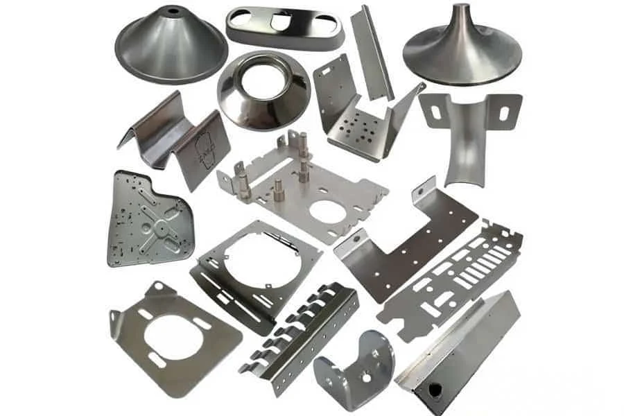
Stainless parts from the same family of tools: drawn shells, formed brackets, pierced panels and mesh frames, each with its own station plan.
Galling, Tool Steel and the Coating Choice
Galling is the failure that separates a stainless stamping programme from a carbon-steel one. Under pressure, the chromium oxide layer that protects the part stops acting as a barrier between the workpiece and the die, and stainless begins to weld to the tool at a microscopic scale: the first pass picks up material, the next tears it, and the surface that results needs polishing and rework. It is a temperature-and-pressure phenomenon, so the countermeasures are aimed at both:
- Tool steel and coating. DC53 hardened and coated with a CVD or TD layer holds the working surfaces far better than uncoated tool steel, and the coating's own low-friction character delays pick-up. Die life in coated tooling is measured in the hundreds of thousands of strokes on stainless, against tens of thousands for an uncoated die in the same duty.
- Die surface finish. Working surfaces polished to around Ra 0.4 µm give the material less to key into, and the parts come off the press with a surface that does not need secondary polishing.
- Cooling and lubrication. Die cooling channels remove heat where it is generated rather than waiting for the press frame to dissipate it, and an extreme-pressure lubricant keeps a film between the surfaces at the contact pressure that actually occurs — which is well above the nominal tonnage figure.
- Speed. Slow enough to keep the interface cool. Difficult stainless work runs in a 15–35 strokes/min window, and that ceiling is a process requirement rather than a limitation of the press.
Where the part is a visible surface, the alternative to controlling galling is polishing every part afterwards, which costs more per piece than the coated die and still leaves the polished surface less uniform than a formed one.
Blanking Clearance, Burrs and Edge Condition
Every pierced or blanked edge is defined by the clearance between punch and die. Run it too tight and the stainless tears, rolling a hard burr on one side and work-hardening the edge; run it too loose and the fracture zone grows, the edge rolls further and the burr gets larger. For 304 and 316L the working range is 6–10% of sheet thickness per side, held consistently on both sides of the punch.
That consistency is a die-making decision, not a press setting. Dies cut on wire EDM hold the clearance the drawing specifies, and it is the reason the clearance value belongs on the tool drawing rather than in a setup note. Downstream, a defined deburring step handles edges that will be handled in assembly or carry current: a rolled burr is a scratch risk for operators and a short-circuit risk in an electrical assembly.
Edge condition also matters to the next process. A laser-cut or sheared edge is work-hardened and slightly rougher than the strip surface, so if that edge will be formed or welded, the process plan should account for it — see how to cut sheet metal for how the cutting route changes the edge, and laser cutting for the fibre process on stainless.
Progressive Dies, Material Yield and Cost
At volume, the die structure decides the unit cost more than the press does. A progressive die performs several operations per stroke — pierce, form, draw, emboss, trim, sometimes tap — and runs at 60–120 strokes/min, which removes handling between operations and keeps every part in the run dimensionally consistent because it saw exactly the same station sequence.
Two cost levers come with that decision:
- Strip layout and nesting. The strip is the largest single line in a stainless part's cost, and a station plan that packs the geometry keeps material utilisation at or above 75%. Rotating a part, sharing a cut between adjacent parts, or changing the number of stations can move more money than a press-speed increase.
- The break-even against simpler tooling. A progressive die costs more to build than a single-hit or compound tool. Whether that is repaid depends on annual quantity, how many forming stations the geometry needs, and how much of the strip can be used — not on a rule of thumb about stroke rate.
Below the break-even, three routes compete: a compound tool with secondary operations, a laser-cut blank that is formed and then deburred, or a low-cost die for a first batch while the design settles. Stainless sheet from 0.05 mm to 3.0 mm is in routine use here; the thinner gauges push the clearance and burr control into a different regime than the heavier ones.
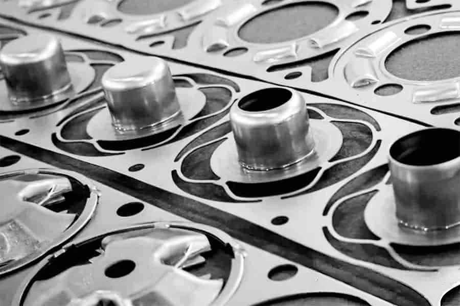
Formed bosses and extruded flanges in the strip. Material utilisation is decided by how these features are nested, not by the press.
What to Measure, and How Often
Stainless stamping fails quietly: a part can be dimensionally correct and still have a wall that has thinned past specification, or a formed corner with micro-cracks that only show up in a pressure or fatigue test. The measurement plan should be built to catch those, not just the outside dimensions.
- First-off inspection against the drawing. Every dimension with a tolerance, by CMM where the callout is geometric, on the first parts off the tool rather than on a sample after the run is running.
- Wall thickness on drawn parts. Section or measure the wall at the punch nose and again at mid-height; that is where the 15% thinning limit is actually consumed.
- Surface finish and edge condition. Ra on decorative or sealing surfaces, and burr height or a defined deburring result on functional edges.
- Coil-to-coil stability. The same part from a new lot, checked before the run continues — hardness and thickness vary between coils, and both move springback.
- Dimensional cadence through the run. A defined interval that is short enough to catch tool wear before it produces out-of-tolerance parts.
Records follow the parts. For a regulated programme that means the inspection report, the material certificate for the specific coil and the finishing certificate travel with the shipment — passivation to ASTM A967 or electropolishing where the drawing calls for it, with the process standard named on the purchase order rather than implied.
Stainless Stamping at SHBD Metal
Stainless stamping here runs on progressive and compound tooling with servo-controlled presses, tooling made in-house on wire EDM so the blanking clearance on the drawing is the clearance in the die. 304 and 316L are the two grades we see most, from 0.05 mm to 3.0 mm, alongside the aluminium and titanium work on the same floor.
Surface treatment is specified rather than assumed: deburring, citric acid passivation to ASTM A967, electropolishing where the drawing calls for it, all through qualified finishing partners with certificates supplied against the order. Inspection covers first-off, dimensional cadence through the run and wall thickness on drawn parts, with material certificates tied to the coil that was used.
On the quality system, plainly: we work to ISO 9001:2015, in place here since 1994, with 150+ people, 100+ machines and 7 dedicated inspectors. If a programme is written around IATF 16949 or ISO 13485, tell us at the RFQ stage so we can confirm whether the route fits instead of implying a certificate we do not hold.
Send the drawing with the material grade, the annual quantity and the surface requirement, and we will come back with the tooling route, the parameters that matter for that geometry and what the strip layout can achieve — see metal stamping, progressive die stamping and quality control. Related reading: warm forming for hard-to-form titanium and which stainless grade to specify.
FAQs
Why is stainless steel harder to stamp than mild steel?
Austenitic stainless work-hardens much faster than low-carbon steel: its strain-hardening exponent sits near 0.45–0.50, and yield strength climbs steeply with every pass. Three consequences follow. The press needs more tonnage for the same geometry, springback is larger and less forgiving, and the material that has already been sheared or laser cut at the strip edge arrives partially hardened, so the first forming station sees a stiffer blank than the material certificate suggests. It also galls: the passive chromium oxide that makes stainless corrosion resistant offers almost no lubricity against a tool steel surface.
How is springback held to ±0.01–0.03 mm?
Two things together: the die face is cut over-bent by the amount the part is predicted to spring back, and the press corrects the rest of the stroke. The prediction comes from a forming model of the actual radius, wall and material lot; the correction comes from a servo-controlled ram that reads its own position and adjusts the bottom dead centre within the stroke rather than assuming the programmed depth. That combination is what makes a ±0.01–0.03 mm band realistic in production instead of in a try-out report, and it is verified on the first-off parts before the run is released.
What actually stops galling in a high-volume stainless run?
Keeping the tool-workpiece interface cool, smooth and lubricated at the same time. In practice that means hardened tool steel with a hard coating — DC53 with a CVD or TD layer is the usual specification — polished to around Ra 0.4 µm, cooling channels designed to pull heat out of the die rather than only out of the press, an extreme-pressure lubricant, and a speed window that keeps contact temperature down: 15–35 strokes/min for difficult stainless work, against the 60–120 strokes/min a progressive die runs when the material allows it. Galling is a temperature and pressure problem before it is a lubrication problem.
Why does 316L crack in deep drawing, and how is thinning limited?
Because a single deep draw asks the material to take all its strain at once, and 316L work-hardens as it goes, so the wall thins in the region that is still being pulled. The fix is to split the draw into several lighter passes so internal stress is released progressively rather than in one step, and to vary blank-holder force through the stroke (low early to let material flow in, higher later to control the wall) instead of holding it constant. Wall thinning is kept inside 15% of nominal and the draw is planned around a strength coefficient in the 0.5–0.55 range for the annealed sheet.
What blanking clearance should 304/316L parts be run at?
Around 6–10% of sheet thickness per side for these alloys, held consistently on both sides of the punch. Too little clearance tears the sheet and rolls a burr edge; too much leaves a drawn-out fracture zone and a larger burr on the opposite side. Dies are cut on wire EDM for that reason — the clearance is a die-making decision as much as a press setting — and where the edge is a mating or electrical surface, a controlled deburring step follows the press rather than relying on the shear alone.
When do progressive dies pay for themselves on stainless work?
When the annual volume justifies the tool and the part's features can be distributed across stations. A progressive die runs several operations per stroke at 60–120 strokes/min, which cuts handling and labour, and a nested strip layout typically keeps material utilization at or above 75%. Below that volume the arithmetic usually favours a simpler single-hit or compound tool with secondary operations, and for very low volumes a laser-cut blank that is formed and then finished often beats a die outright. The honest answer comes from three numbers: annual quantity, the number of forming stations the geometry really needs, and how much of the strip the nesting can use.
Summary
Stainless stamping is a set of problems with named controls: springback held by over-bend compensation and closed-loop ram control, galling held by coated tool steel, polished die surfaces, cooling and an EP lubricant inside a defined speed window, thinning held by splitting the draw and varying the blank-holder force, and burrs held by blanking clearance at 6–10% of thickness per side with a planned deburring step. None of it depends on a special press. It depends on the tool being designed for the alloy rather than for carbon steel and then validated on first-off parts.
Specify 316L when the part sees chlorides, body fluids or sterilisation, and 304 when it does not; specify the surface treatment as a standard rather than as an adjective; and size the tool to the annual quantity instead of the reverse — a progressive die at 60–120 strokes/min and 75% strip utilisation is the right answer at volume and the wrong one at 5,000 pieces. Send the drawing and the volume, and we will tell you which side of that line your part sits on — request a quote.


Comment
0 comments
Got thoughts or experiences to share? We’d love to hear from you!