

Every dimension on a microwave housing comes back from the drawing office carrying the same tight band, and the quotation that follows is expensive for no electrical reason. Only one region of the part sets the frequency it will run at: the cavity. The rest of the housing exists to hold that cavity square, keep coolant and connectors where they belong, and survive handling — and none of those jobs need micrometre callouts.
This guide separates the two, feature by feature: which faces a RF enclosure tolerance band actually governs, what happens at a seam when the band slips, how much roughness the cavity walls can carry before the skin effect notices, and how the alloy and the set-up count decide whether the band survives the cut.
What this guide covers
- Two bands, not one. Cavity walls and knife-edges live at ±0.005–±0.01 mm; mounting frames, cover faces and feet are comfortably coarse. Treating the whole drawing as cavity is the single most common way to overpay for a housing.
- Shielding follows joint geometry. Radiation escapes through seam length and gasket compression, so a flange held flat to 0.01 mm buys more isolation than a wall machined 0.003 mm tighter.
- Roughness is an electrical callout. Inside the cavity it sits between Ra 0.4 µm and Ra 0.8 µm because the current rides in a skin only micrometres deep.
- Alloy and set-up decide the outcome. Pre-stretched 7075-T651 plate plus a single five-axis clamping removes most of the ways a tight band drifts after the cut.
What a Tolerance Band on an RF Housing Really Controls
A cavity resonates because its dimensions fix the capacitance and inductance of the enclosed volume. Move a wall and the resonant frequency moves with it, which is why the cavity wall on a microwave housing is not a mechanical feature at all — it is an electrical one, expressed in millimetres. Machining tolerance on that wall is therefore the accuracy with which the electrical behaviour is reproduced.
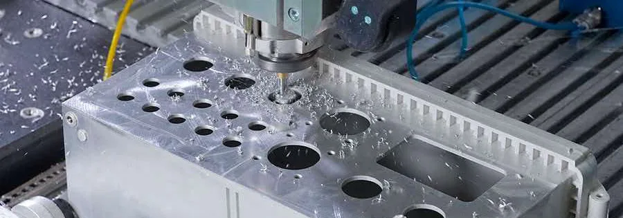
Cutting the cavity side of an aluminium housing. These walls set resonance, so they are the faces that earn the tight band — the outer frame does not.
Band by band, the housing splits like this:
- ±0.005 mm to ±0.01 mm (IT5–IT7) — cavity walls, partition knife-edges and coaxial blind bores, where the dimension sets frequency.
- ±0.01 mm to ±0.05 mm (IT8–IT10) — connector seats and mating flanges that have to locate a part or seal a joint, but do not define it.
- ±0.1 mm and wider (IT11 and up) — mounting feet, outer walls and nameplate slots, held by convention rather than by function.
ISO 286-1 is where those numbers come from: it maps every linear size to an International Tolerance grade, so a callout can be written as IT6 on a 20 mm cavity rather than a bare number that means something different on a 200 mm frame. Anything the drawing leaves blank falls back to the general tolerances of ISO 2768-1:1989, which is usually wide enough for every face that is not doing electrical work. The habit worth breaking early is assuming the strictest value on the sheet applies everywhere; on a typical housing, the majority of walls never see it.
Why the Seam, Not the Wall, Decides Shielding
Microwave energy does not leak through metal. It leaks through the gap where two pieces of metal meet: a seam whose length approaches a quarter wavelength behaves like a slot antenna and radiates. That single fact reorders the drawing. Wall thickness has almost nothing to do with attenuation, while flange flatness and gasket compression have nearly everything.
Two consequences follow for machining:
- Flange flatness to ≤0.01 mm. A mating face that is flat within a hundredth of a millimetre closes along its whole length. Any bow leaves a tapered gap that grows into a slot radiator as frequency climbs into X-band and Ka-band.
- Gasket groove depth to the same band. A conductive elastomer gasket only seals while it is evenly compressed, and depth sets that compression. Cut the groove 0.03 mm deep and the gasket sits slack in the middle of the joint; hold it with the flange faces at ±0.01 mm and the joint stays closed across its length.
Current path is the test to apply when deciding where a band belongs. Surface current crosses the joint and nowhere else, so the faces it follows get the tight band, and the outer frame — which the current never touches — does not. In practice that means cavity joints and gasket grooves at ±0.01 mm, and mounting feet deliberately coarse at ±0.05 mm or wider.
Cavity Size, Skin Depth and the Ra Window
Resonance is inversely proportional to cavity dimensions, so a wall that moves by ten micrometres shifts the frequency the cavity was designed to hit. The same logic applies to the surface inside it. At high frequency the current concentrates in a thin outer layer, and where the peaks of the machined texture reach through that layer, the effective path lengthens and loss climbs.
| Surface texture | Relation to the current skin | Loss outcome | Faces it applies to |
|---|---|---|---|
| Ra 0.4–Ra 0.8 µm | Peaks stay inside the skin layer | Return loss stays predictable; Q holds | Cavity floor, cavity side walls |
| Ra 1.6 µm | Peaks reach the skin layer | Insertion loss begins to climb | Mating flange, heat-sink base |
| Ra 3.2 µm | Peaks break through the skin layer | Resonance damps, Q falls away | Outer cover, nameplate slot |
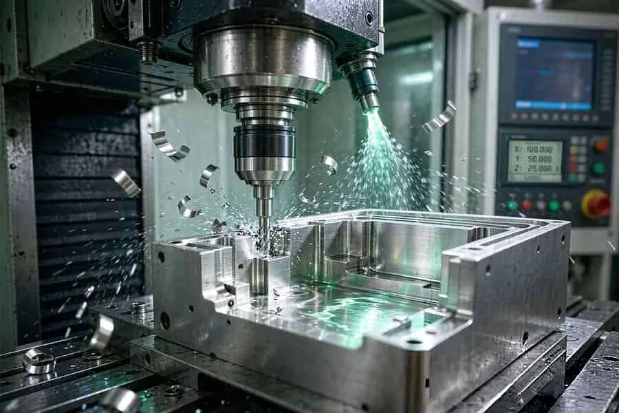
Cavity machining under flood coolant. Floor and walls come off the finishing pass at Ra 0.4–Ra 0.8 µm, which is a finish callout rather than a dimensional one.
Skin depth is not the same thing as roughness height, although the two get confused on the shop floor: one describes how deep the current penetrates, the other describes the texture left by the cutter. They interact, which is why finish and dimension are specified together on a cavity and separately on a frame. Inspection follows the same split. A standard band on a frame can be verified with a calliper or a height gauge, while a plasma or optical scan will not settle a flatness callout on a flange — that needs probing against a datum, with the probe error budget coming from the ISO 10360 series.
How Alloy Choice and Residual Stress Move a Wall
Aluminium expands roughly twice as much as steel per degree, which is a gift on a housing: the material is light and machines fast. It is also the reason a tight band fails after the cut rather than during it. Rolling and heat treatment lock residual stress into the plate, and every pass that removes stock from one side releases it, so the wall bends away from the cutter in small, quiet increments.
Two grades carry most RF housing work:
- 7075-T651 — pre-stretched during production, so much of the internal stress is already gone before machining starts. It is the grade for ultra-thin cavity walls and knife-edges where movement of a few micrometres would detune the cavity.
- 6061-T6 — lower strength and lower stress, easier on thin ribs and cheaper per kilogram. It suits covers, frames and housings whose cavity is not the critical feature.
The process answer is the same for both. Rough out leaving stock, stress-relieve by annealing before the finishing pass, then finish with parameters selected for heat: on wrought aluminium the finishing speed typically sits near Vc = 60 m/min, where the cut stays cool enough that thermal growth does not add to the mechanical movement. Run it hard and the part grows under the cutter; run it slow and the cutting force rises until thin ribs deflect.
The verification is deliberately boring. Measure the cavity depth when the finishing pass ends and again the next morning. Two readings that match mean the wall has settled; a difference of a few micrometres means the stress is still working and the housing should not be signed off. Blanket tight tolerances do not fix this — they simply add inspection hours to a part that was going to move anyway.
Standard or Tight: Machine Class and Inspection Depth
Once the bands are split, the machine decision almost makes itself. A standard band of ±0.01 mm to ±0.05 mm on an outer frame is routine work for a three-axis vertical machining centre. The tight cavity band is not impossible on three axes, but it costs accuracy: every face change means re-clamping, and each new set-up resets the datum that flatness is measured against.
A five-axis simultaneous centre reaches five faces in one clamping, so the cavity, the flange and the connector seats are all cut against the same datum — which is what makes a flatness callout meaningful rather than nominal. Three checks decide whether a callout earns the tight band:
- Does surface current cross it? Cavity walls and gasket grooves do; feet and covers do not.
- Is it reached in one set-up? Faces cut with the part clamped once keep datum continuity; faces that need a re-clamp carry the error of two set-ups.
- What does verifying it cost? A tight band means full probing of the datum features and a CMM report that travels with the batch, not a calliper reading.
That last point is the one purchasing teams feel. Inspection depth tracks the band, so a drawing that pulls the cavity tolerance onto every face multiplies the probing work for no gain in electrical performance. Grading the callouts — tight where the current runs, standard everywhere else — is the practical way to hold the price of a housing down without touching the parts that matter.
Picking a Band Feature by Feature
The four groups below cover the features that appear on most RF and microwave housings. Assigning a band by group, rather than by drawing section, is what keeps the tight callouts to the faces that deserve them.
| Feature group | Resonant cavity wall | Knife-edge seam | Mounting flange | Outer, non-mating face |
|---|---|---|---|---|
| Size envelope | ±0.005–±0.01 mm | ±0.005–±0.01 mm | ±0.01–±0.05 mm | ±0.1 mm |
| Electrical role | Sets resonance, holds impedance | Closes the seam against slot radiation | Carries frame rigidity and mounting holes | Protection and dust exclusion only |
| Surface finish | Ra 0.4–0.8 µm | Ra 0.4–0.8 µm | Ra 1.6 µm or coarser | No electrical requirement |
| Typical hardware | Satellite microwave channel | Airborne radar combiner | Base-station frame | Industrial motor cover |
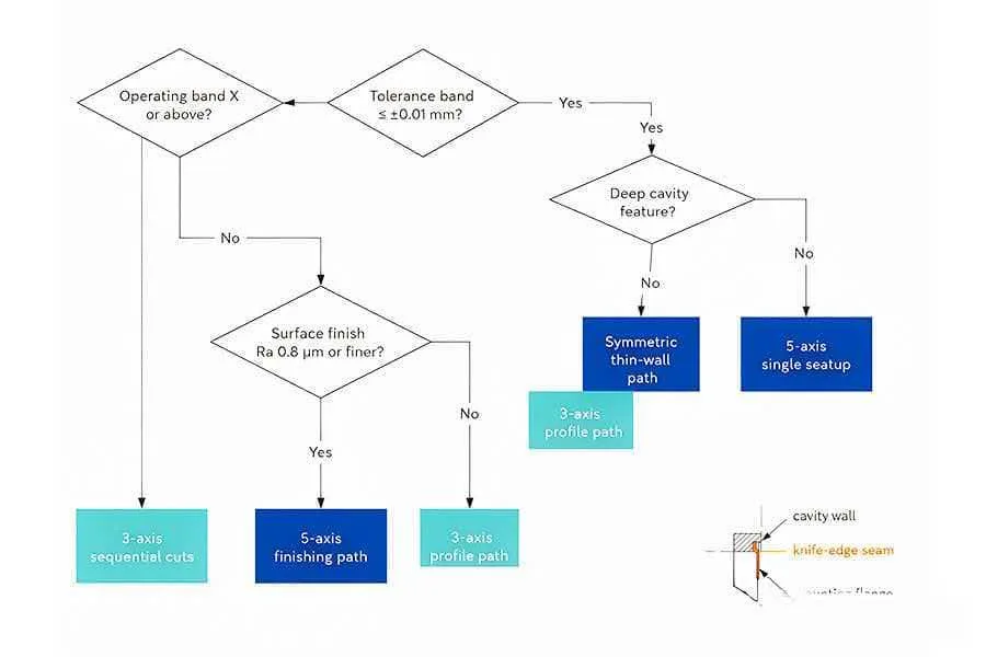
The path our planners walk: band first, then cavity depth, then finish. A shallow, wide-open cavity rarely justifies a simultaneous five-axis cut, while deep knife-edge geometry usually does.
Read the tree from the band outwards. Anything at ±0.01 mm or tighter on a feature with a surface-current path is planned for a single-setup five-axis route, because re-clamping is the main source of error at that scale. Symmetric thin walls follow the same route; asymmetric, shallow profiles can be profiled on three axes with sequential cuts and stay inside band. Where the finish callout is Ra 0.8 µm or finer, the finishing pass is planned separately from roughing so the cutter runs at finishing feed rather than being asked to do both jobs at once.
For a housing that is mostly frame with one shallow cavity, that decision alone can move the quoted price materially while leaving the resonance behaviour untouched.
In Practice: A Dual-Cavity X-Band Converter
The pattern shows up on almost every X-band programme. A customer arrives with a dual-cavity converter housing in 7075-T651 pre-stretched plate, and the first drawing carries the tight band on every dimension — cavity depth, knife-edge, flange, mounting feet, even the nameplate slot.
The DFM review that follows is not an argument about capability; it is an exercise in sorting by function:
- Cavity depth and the mating knife-edge keep ±0.005 mm to ±0.01 mm, because together they set the resonant frequency the converter was designed around.
- Cavity walls keep the Ra 0.6 µm finish callout, since the skin effect is what turns a rough floor into insertion loss.
- The partition seam holds ≤0.01 mm flatness so the two cavities stay isolated from each other.
- Frame outline, cover mountings and feet move to standard bands, because no surface current runs along them.
Machining then follows the sequence from the previous sections: rough with stock left on, anneal to shed the stress the roughing released, finish at a cutting speed that keeps heat out of the wall, and measure the cavity the next day before the part is released. The gain is not tighter parts — the critical faces were always going to be tight — it is that the rest of the housing stops being inspected to a band it never needed. Teams that make this split report a shorter route through inspection and a lower unit cost, because the extra work was concentrated in programming and probing decisions rather than in metal removal.
Two steps carry most of that result. Pick the band from the current path, and verify only what the band promises: flange flatness and gasket groove depth at the joint, cavity depth against the pre-cut record, and standard gauge checks on the frame.
RF and Microwave Housings at SHBD Metal
We have been machining since 1994, with 150+ staff, more than a hundred machines and a seven-person quality team working to an ISO 9001:2015 quality system. RF and microwave housings run on our five-axis machining centres, with the cavity, flange and connector seats cut in one clamping, and they sit alongside the general work described under CNC milling and CNC machining. Certified material comes with each batch of 7075-T651 plate, and the CMM reports travel with the parts.
Send the model or drawing with the bands as they stand, plus the frequency range the cavity has to hold. The DFM reply says which callouts our machining can meet, which ones we would move to a wider band and why, and where a design change would remove inspection work without touching the electrical behaviour. If the programme needs a certified automotive or aerospace QMS from the production supplier, say so at that stage and we will tell you straight whether we fit.
Have a housing with tolerance bands you are unsure about?
Send the Drawing for DFM ReviewFAQs
What tolerance should an RF or microwave housing be quoted to?
Quote it band by band instead of naming one number. The resonant cavity — walls, partition knife-edge, coaxial blind bores — carries ±0.005 mm to ±0.01 mm, mating connector seats sit at ±0.01 mm to ±0.05 mm, and mounting feet run coarse at ±0.1 mm or wider. ISO 286-1 puts those bands on an IT scale — IT5 to IT7 for the cavity, IT11 and up for the feet — and ISO 2768-1 supplies the default band for whatever the drawing leaves unlabelled. One number for the whole part forces the cavity band onto faces that never needed it.
Does surface roughness carry the same weight as the dimensional band?
Inside a cavity it does, because at microwave frequencies the current travels in a skin a few micrometres deep and roughness peaks poke straight through it. Cavity floors and side walls are held around Ra 0.4–Ra 0.8 µm to keep return loss predictable, mating flanges are fine at Ra 1.6 µm because they carry no current across the joint, and an outer cover at Ra 3.2 µm is electrically irrelevant. Roughness is a finishing callout, not a dimensional one — a wall can hold its band and still ruin Q if the finish is wrong.
Can a three-axis machining centre hold the tight RF band?
Often not, and the reason is set-up count rather than machine accuracy. A three-axis vertical centre machines X, Y and Z, so every new face means a re-clamp and a fresh datum; flatness then depends on how well the two set-ups agreed. A five-axis simultaneous centre reaches five faces in one clamping, which is what keeps flange flatness tied to a single datum the way ASME Y14.5-2018 describes it. Send us the drawing and we will say which bands our five-axis work can hold and which callouts the geometry makes awkward.
How do you keep a thin wall from springing back during the finishing pass?
By separating roughing from finishing in time, not just in depth. Rolling and heat treatment leave residual stress in the plate, and roughing releases it, so the wall moves after the cutter leaves. The sequence that works is rough, stress-relieve, then finish — with finishing parameters held near Vc = 60 m/min in aluminium so the cut adds as little heat as possible. We measure the cavity depth a day after finishing as well: if the second reading matches the first, the wall has stopped moving.
Which standards should the callouts reference?
ISO 2768-1:1989 for the general tolerances that cover unlabelled dimensions, ISO 286-1 for linear size bands, ASME Y14.5-2018 for the geometric callouts and datum scheme, and the ISO 10360 series if a CMM report is going to be your acceptance record. The quality system behind them is a separate question: we work to an ISO 9001:2015 system, and if your programme requires a certified automotive QMS from the production supplier — rather than IATF 16949 being mentioned as a nice-to-have — tell us at RFQ stage and we will say plainly whether we fit.
Summary
An RF housing has two kinds of dimension on it. The ones that set resonance — cavity walls, knife-edges, the faces surface current crosses — belong at ±0.005 mm to ±0.01 mm with a finish inside Ra 0.4–0.8 µm. Everything else is structure, and structure is served by standard bands and a calliper. Sorting the drawing that way, then choosing a single-setup five-axis route for the critical faces and a stable aluminium grade for the walls, is what keeps both the resonance and the price where they were meant to be.



Comment
0 comments
Got thoughts or experiences to share? We’d love to hear from you!