Estimating machining tolerances and their associated costs without a clear standard often leads to misaligned expectations and budget overruns. Guessing the wrong precision level typically results in either expensive scrap or paying for unnecessary machining time. We analyzed thousands of CNC projects at RapidDirect to map out exactly how standard tolerances impact both manufacturability and price. For engineers and procurement managers looking to lock down precise specifications, here is the complete ISO 2768 tolerance chart breakdown to guide your next manufacturing run.
The Complete ISO 2768 Tolerance Chart
When a CNC part drawing lacks specific tolerances for individual dimensions, the ISO 2768 standard dictates the acceptable deviation limits. This standard is divided into two parts: ISO 2768-1 for linear and angular dimensions, and ISO 2768-2 for geometric tolerances.
ISO 2768-1 Linear Tolerances
This table applies to external/internal sizes, step lengths, diameters, and distances. Dimensions under 0.5mm must always have a custom tolerance explicitly stated on the drawing.
| Nominal Dimension (mm) | f (Fine) | m (Medium) | c (Coarse) | v (Very Coarse) |
| 0.5 up to 3 | ±0.05 | ±0.10 | ±0.20 | N/A |
| Over 3 up to 6 | ±0.05 | ±0.10 | ±0.30 | ±0.50 |
| Over 6 up to 30 | ±0.10 | ±0.20 | ±0.50 | ±1.00 |
| Over 30 up to 120 | ±0.15 | ±0.30 | ±0.80 | ±1.50 |
| Over 120 up to 400 | ±0.20 | ±0.50 | ±1.20 | ±2.50 |
| Over 400 up to 1000 | ±0.30 | ±0.80 | ±2.00 | ±4.00 |
| Over 1000 up to 2000 | ±0.50 | ±1.20 | ±3.00 | ±6.00 |
| Over 2000 up to 4000 | N/A | ±2.00 | ±4.00 | ±8.00 |
ISO 2768-1 Radius and Chamfer Tolerances
Use this reference for external radii and chamfer heights.
| Nominal Dimension (mm) | f (Fine) & m (Medium) | c (Coarse) & v (Very Coarse) |
| 0.5 up to 3 | ±0.20 | ±0.40 |
| Over 3 up to 6 | ±0.50 | ±1.00 |
| Over 6 up to 30 | ±1.00 | ±2.00 |
ISO 2768-1 Angular Tolerances
Angular tolerance limits are determined by the length of the shortest side forming the angle.
| Shortest Side Length (mm) | f (Fine) & m (Medium) | c (Coarse) | v (Very Coarse) |
| Up to 10 | ±1° | ±1°30′ | ±3° |
| Over 10 up to 50 | ±0°30′ | ±1° | ±2° |
| Over 50 up to 120 | ±0°20′ | ±0°30′ | ±1° |
| Over 120 up to 400 | ±0°10′ | ±0°15′ | ±0°30′ |
| Over 400 | ±0°5′ | ±0°10′ | ±0°20′ |
ISO 2768-2 Geometric Tolerances
Part 2 of the standard controls shape and position. The classes here are H (High), K (Medium), and L (Low). You will frequently see these combined with Part 1, resulting in drawing callouts like ISO 2768-mK.
Straightness and Flatness
| Nominal Length (mm) | H (High) | K (Medium) | L (Low) |
| Up to 10 | 0.02 | 0.05 | 0.10 |
| Over 10 up to 30 | 0.05 | 0.10 | 0.20 |
| Over 30 up to 100 | 0.10 | 0.20 | 0.40 |
| Over 100 up to 300 | 0.20 | 0.40 | 0.80 |
Perpendicularity
| Nominal Length (mm) | H (High) | K (Medium) | L (Low) |
| Up to 100 | 0.20 | 0.40 | 0.60 |
| Over 100 up to 300 | 0.30 | 0.60 | 1.00 |
| Over 300 up to 1000 | 0.50 | 0.80 | 1.50 |
Decoding the ISO 2768 Tolerance Classes
Fine (f) vs. Medium (m)
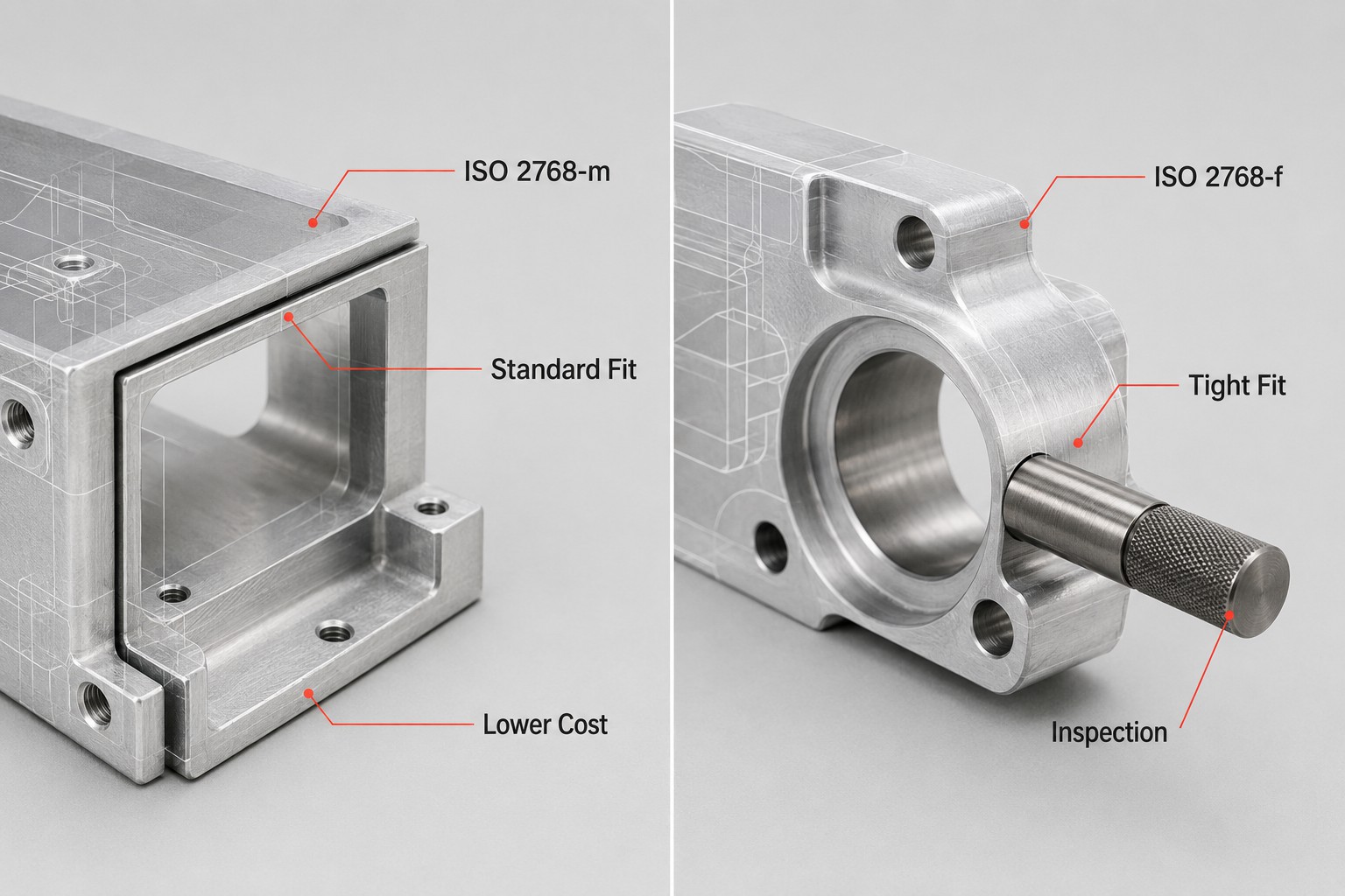
The ISO 2768-m tolerance is the undisputed industry standard for most CNC machined parts. It strikes an optimal balance between precision and manufacturing cost. You should specify this class for generic enclosures, brackets, and non-critical metal or plastic components.
The ISO 2768-f tolerance chart is reserved for high-precision requirements. You will specify this for bearing housings, sealing surfaces, and critical mating parts. Because it requires tighter tool control, slower feed rates, and rigorous inspection, selecting “f” will predictably increase your component cost.
Pro Tip: If your material is plastic, default to the ISO 2768 medium tolerance (m). Plastics are highly susceptible to thermal expansion and moisture absorption, making “f” class tolerances virtually impossible to hold consistently without utilizing expensive engineering resins like Polycarbonate.
Coarse (c) and Very Coarse (v)
The ISO 2768-c tolerances are appropriate for non-mating exterior surfaces or protective covers. The “v” class is almost exclusively used for large-scale sheet metal fabrication, heavy welding, or rough cast blanks. Never specify “v” for a precision CNC milling or turning operation.
How Manufacturing Processes Impact ISO 2768 Tolerance Choices
CNC Milling Constraints
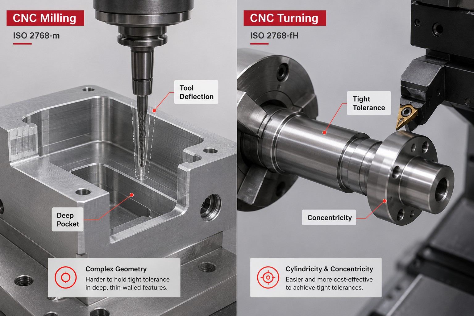
Milling relies on rotating cutting tools to remove material from a stationary block. While CNC milling handles complex cavities and multi-axis features brilliantly, holding an ISO 2768 mk tolerance across a deep, thin-walled pocket is difficult. The longer the cutting tool, the more it deflects. Limit deep pockets and assign custom, looser tolerances to those specific features while maintaining a general ISO 2768-m standard for the rest of the part.
CNC Turning Dynamics
Turning spins the material against a stationary tool. This makes it incredibly efficient at holding tight dimensional and geometric tolerances (like cylindricity and concentricity) on shafts and flanges. An ISO 2768-fH tolerance is generally much easier and cheaper to achieve on a lathe than on a 3-axis mill, provided the part does not exceed a length-to-diameter ratio of 10:1.
Cost and DFM Strategies for ISO 2768 Tolerance
Blindly slapping a tight tolerance block on a drawing is the fastest way to inflate your procurement budget. Every step up in precision requires more setup time, slower machining speeds, and advanced metrology equipment like CMMs (Coordinate Measuring Machines).
The smartest engineering strategy is a hybrid approach. Call out a baseline general tolerance ISO 2768 pdf standard (like ISO 2768-mK) for the entire drawing. Then, manually override that standard by explicitly dimensioning the 2 or 3 critical features (like an O-ring groove or a bearing press-fit) with custom, tighter limits.
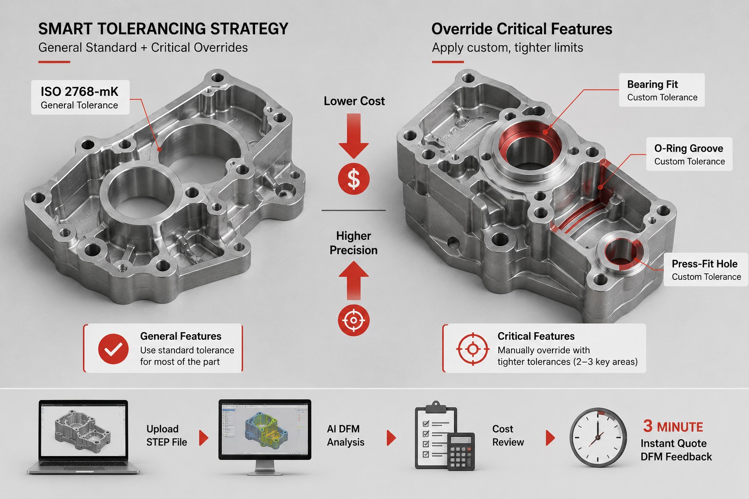
You can automate this cost-benefit analysis using digital tools. You can calculate this manually, OR you can upload your STEP file to RapidDirect’s instant quote engine to get this DFM analysis automatically in seconds. RapidDirect’s AI-driven quoting engine returns exact prices and DFM feedback in about 3 minutes, significantly faster than the 1-2 days required by traditional competitors.
When to Abandon ISO 2768 Tolerance
High-Precision Fits (ISO 286)
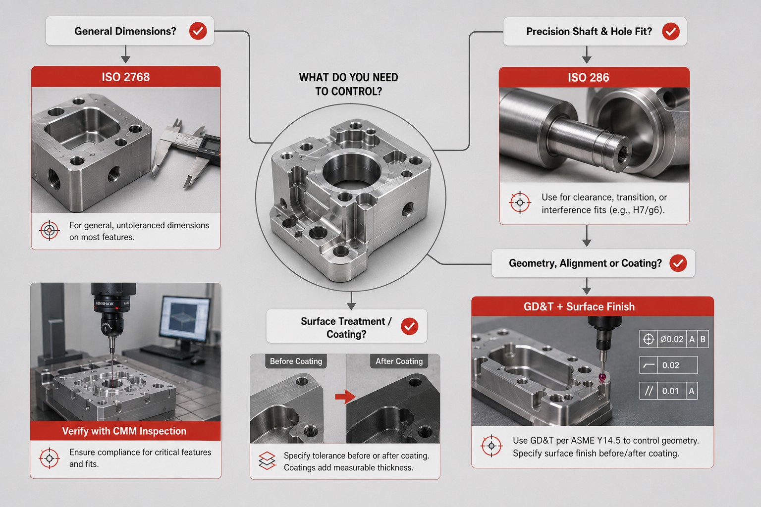
ISO 2768 is explicitly for un-toleranced dimensions. If you are designing precision shafts and holes that must fit together perfectly, you must use the ISO 286 standard instead. This standard uses alpha-numeric codes (like H7/g6) to define clearance, transition, or interference fits. For example, RapidDirect frequently machines parts to strict ISO 286 IT6 or IT7 limits for automotive and medical clients.
Surface Finishes and GD&T
If your part requires anodizing, powder coating, or electroplating, you must specify whether your ISO 2768 tolerance applies before or after the surface treatment. Coatings add measurable thickness. Additionally, if your part requires exact multi-plane alignments, transition away from basic linear tolerances. Instead, use a robust GD&T (Geometric Dimensioning and Tolerancing) framework per ASME Y14.5 to control the feature control frames directly.
Summary
The ISO 2768 standard prevents confusion between design and manufacturing teams by providing a baseline for acceptable deviations. Standardizing on ISO 2768-mK for general features and manually tightening only the critical interfaces will keep your project on budget and on schedule.
If you are ready to validate your design’s manufacturability against these tolerances, upload your CAD file to RapidDirect today. Our platform provides free DFM analysis and instant quoting in minutes, ensuring your precision parts are manufactured exactly to spec with lead times as fast as 1 day.
Frequently Asked Questions
ISO 2768-m defines only the linear and angular tolerances (Part 1). ISO 2768-mK combines the medium linear tolerance (m) with the medium geometric tolerance (K) from Part 2.
Yes. DIN ISO 2768 is simply the German adoption of the exact same international standard. The values and classes are identical. RapidDirect’s standard CNC tolerance defaults to ISO 2768-m (±0.1mm), with precision tolerances down to ±0.01mm available upon request.
No. The standard explicitly states that nominal dimensions below 0.5mm cannot use these general tables. You must provide a specific tolerance adjacent to that dimension on your drawing.
To guarantee an “f” class tolerance, machinists must account for tool wear, machine vibration, and thermal expansion inside the CNC cabinet. It often requires taking multiple finishing passes and utilizing 100% CMM inspection, which drives up machine time and labor costs.
Generally, yes. Modern CNC centers hold ±0.1mm (ISO 2768-m for most sizes) easily. However, very large parts (over 400mm) or highly complex geometries might still challenge this standard, making upfront DFM analysis critical.