Estimating CNC machining costs without a factory quote often feels like guesswork, leaving engineers to default to hyper-precise tolerances that unintentionally inflate production budgets. Underestimating the financial impact of a single decimal-place shift now means facing painful redesigns or budget rejections later during sourcing. We analyzed thousands of manufacturing runs to map exactly how tight precision limits scale cycle times, inspection overhead, and scrap rates. For engineering and procurement teams looking to balance mechanical performance with aggressive cost targets, this guide provides the exact cost multipliers and CNC Design for Manufacturability (DFM) strategies you need.
CNC Tolerance Cost Multiplier Reference
The table below outlines how tightening tolerances from a standard rough-machined baseline of ±0.030″ or ±0.76 mm scales your base machining costs.
| Tolerance (Inches) | Tolerance (Metric) | Cost Multiplier | Required Machining Process & QC Intensity |
| ±0.030″ | ±0.76 mm | 1.0x (Baseline) | Rough vertical milling/turning, high feed rates, standard caliper check. |
| ±0.010″ | ±0.25 mm | 1.0x – 1.1x | Standard CNC milling/turning. Highly cost-effective for non-mating features. |
| ±0.005″ | ±0.13 mm | 1.3x | Standard precision machining. Clean surface finishes with standard tooling. |
| ±0.003″ | ±0.08 mm | 1.8x | Semi-finishing passes required. Higher tool wear and more setup attention. |
| ±0.002″ | ±0.05 mm | 2.5x | Rigorous workholding, high-quality carbide tooling, slowed feed rates. |
| ±0.001″ | ±0.025 mm | 3.5x | Precision finishing cuts. Coordinate Measuring Machine (CMM) verification. |
| ±0.0005″ | ±0.012 mm | 5.0x | Climate-controlled workshop, dynamic tool balancing, 100% metrology inspection. |
| ±0.0001″ | ±0.0025 mm | 10.0x – 24.0x | High-precision cylindrical grinding, honing, lapping, and high scrap risk. |
Material and Part Geometry Effects on CNC Tolerance Costs
The relationship between tolerance and manufacturing cost is strictly exponential rather than linear. Modern CNC machinery has made achieving consistent quality more accessible, but the fundamental physical constraints of material removal, thermal expansion, and mechanical deflection still dictate a steep pricing curve as precision demands increase.
Why High Precision Drives Up Price
When you specify a tolerance tighter than ±0.002″ (±0.05 mm), you force the machine shop to change its standard operational workflow.
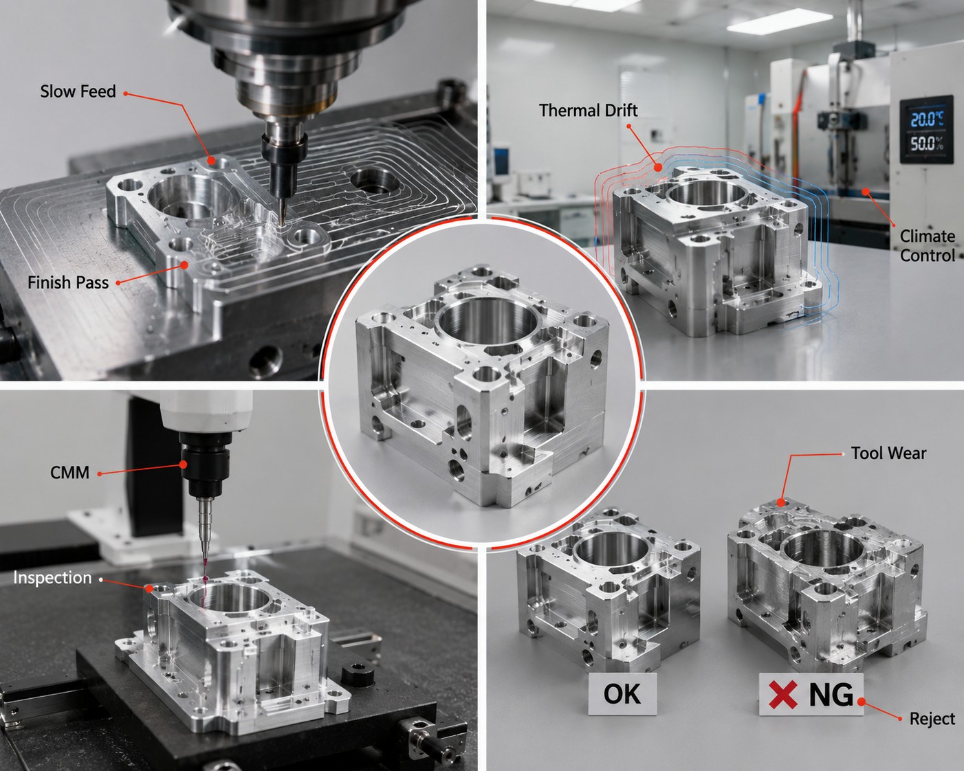
- Slower Cycle Times: To hold tight boundaries, operators must decrease the depth of cut and slow down the feed rate. This adds multiple finishing passes, dramatically extending the time a part occupies the CNC spindle.
- Environmental Control Requirements: Aluminum expands and contracts significantly with temperature changes. A 300 mm aluminum part will shift by 0.07 mm with a temperature fluctuation of just 10°C. Holding sub-mil tolerances requires a temperature-controlled metrology lab and climate-controlled machining bays.
- Complex Inspection & Metrology: Standard digital calipers or micrometers cannot reliably verify dimensions below ±0.001″. Machinists must transfer parts to a Coordinate Measuring Machine (CMM). Part setup, programming, and thermal stabilization on a CMM adds direct labor hours and extends lead times.
- Skyrocketing Scrap Rates: When the acceptable margin of error is extremely narrow, even minor tool wear, thermal drift, or material stresses can push a part out of spec. You pay not only for the accepted parts but also for the cost of the scrapped material and wasted machine hours.
Material and Complexity Factors
The final cost of a high-precision part is a product of tolerance, material machinability, and geometry.
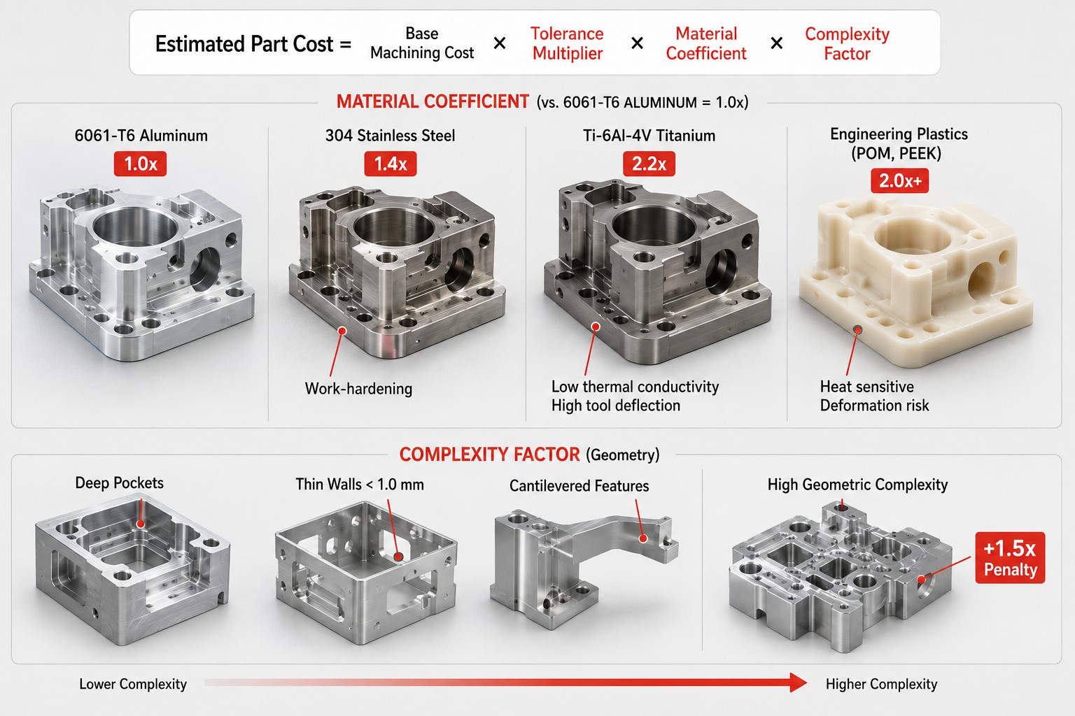
Using standard 6061-T6 Aluminum as a 1.0x material baseline, harder or more abrasive alloys scale the effort required to hold tight tolerances:
- 304 Stainless Steel: 1.4x difficulty multiplier due to work-hardening properties.
- Ti-6Al-4V Titanium: 2.2x difficulty multiplier because of low thermal conductivity and high tool deflection.
- Engineering Plastics (POM, PEEK): Highly sensitive to heat during machining. Standard cutting forces can deform the material, making sub-mil tolerances exceptionally difficult to maintain without specialized cooling and custom fixtures.
- Part Geometry: Deep pockets, thin-walled structures (less than 1.0 mm), and cantilevered features introduce vibrational chatter. If a part has high geometric complexity, expect an additional 1.5x penalty on top of your tolerance multiplier.
GD&T: The Key to Lowering CNC Machining Costs
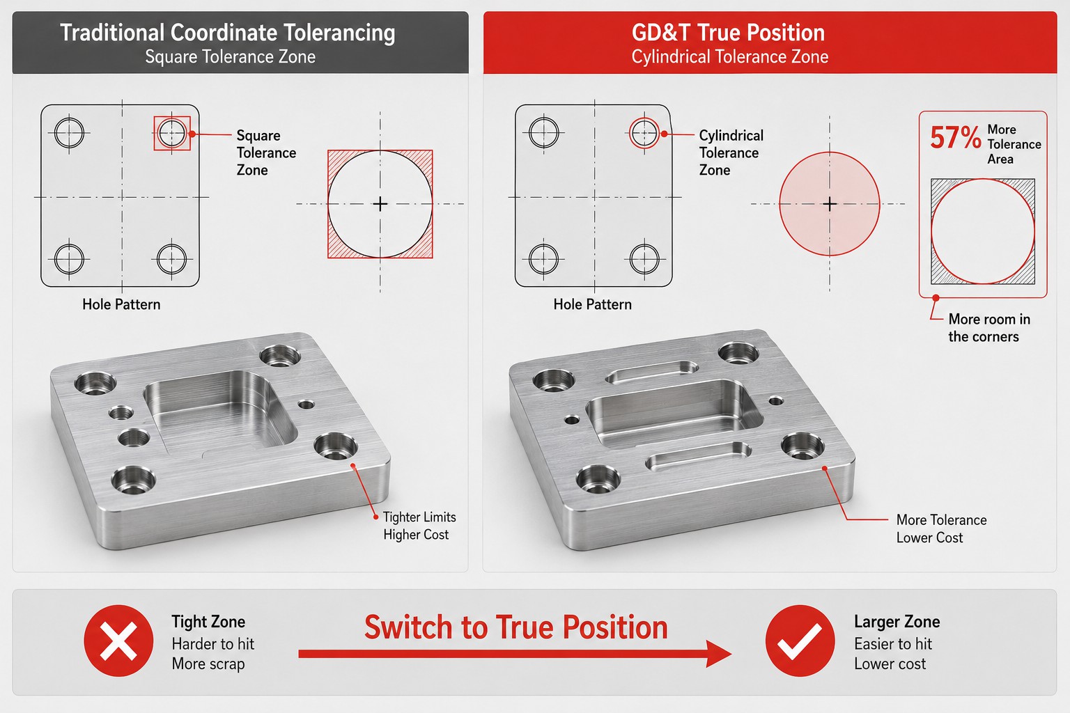
Traditional coordinate tolerancing (using standard ± linear dimensions) defines a square or rectangular tolerance zone. When locating features like hole patterns, this square zone forces engineers to make the tolerance limits artificially tight to ensure fitment at the worst-case corners.
Geometric Dimensioning and Tolerancing (GD&T) uses True Position to define a cylindrical tolerance zone. This circular boundary matches how physical bolts and pins actually fit into mating holes.
By switching to True Position, you gain 57% more tolerance area in the diagonal corners of the zone without compromising the physical assembly’s function. This expanded zone makes it easier for CNC operators to pass parts, directly lowering production costs and reducing scrap.
GD&T Impact on Machining and Cutting Operations
The table below contrasts how GD&T parameters affect machining setups and QC measurements compared to standard linear dimensions.
| Tolerance Type | Machining Setup Impact | Metrology & Inspection Approach | Best Use Case |
| Linear Dimension | Straightforward tool paths. Low programming overhead. | Simple measurement using calipers, micrometers, or go/no-go gauges. | Clearances, overall stock dimensions, basic pocket depths. |
| Profile of a Surface | High programming time. Demands synchronized multi-axis tool control. | Requires full CMM scanning or optical comparators. | Complex aerodynamic surfaces, ergonomic grips, mold cavities. |
| True Position | Moderate setup complexity. Requires rigid workholding and precise zeroing. | Functional pin gauges or CMM hole-center verification. | Bolt circle patterns, mating alignment pins, multi-part assemblies. |
| Flatness | Demands light cuts, sharp tooling, and tension-free workholding. | Dial indicator sweeps or CMM surface mapping. | Dynamic sealing faces, heatsink mounting planes. |
| Perpendicularity | Requires precise squareness alignment during machine setup. | Square blocks, sine bars, or multi-axis CMM checks. | Vertical mounting brackets, structural columns. |
Strategic Tolerance Tiering (DFM)
A highly cost-effective design reserves tight tolerances only where they are functionally necessary. Assigning a global block tolerance (e.g., blanket ±0.002″ in the drawing title block) to an entire part is a primary driver of unnecessary manufacturing costs.
Setting up a Tiered Tolerance Structure
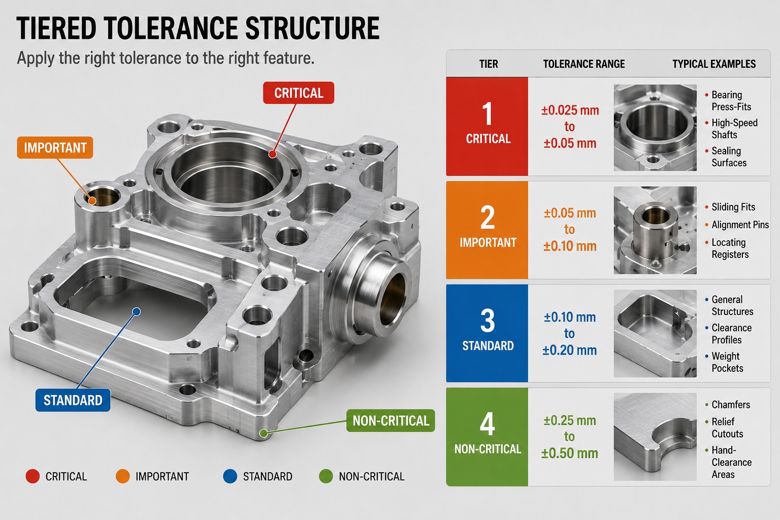
Divide your part features into four distinct tiers to optimize manufacturing efficiency:
- Critical Tolerances (±0.025 mm to ±0.05 mm): Apply these strictly to mating interfaces, such as bearing press-fits, high-speed rotating shafts, and metal-to-metal sealing surfaces.
- Important Tolerances (±0.05 mm to ±0.10 mm): Use these for sliding fits, alignment pin locations, and locating registers.
- Standard Tolerances (±0.10 mm to ±0.20 mm): Follow standard industrial standards like ISO 2768-m. These are suitable for general structural features, external clearance profiles, and weight-reduction pockets.
- Non-Critical Tolerances (±0.25 mm to ±0.50 mm): Apply these to cosmetic chamfers, relief cutouts, and hand-clearance areas.
Assembly Optimization and Datum Best Practices
Instead of demanding tight tolerances on every single component, optimize your assembly structure to absorb dimensional variations:
- Design Stable Datums: Select a primary datum that is a large, flat, easily machinable surface. This surface should directly interface with mating parts in the final assembly. Secondary and tertiary datums should be positioned close to critical features to prevent long tolerance chains.
- Design for Clearance: Whenever possible, use standard clearance holes for fasteners. Increasing a clearance hole diameter from 4.2 mm to 4.5 mm allows you to loosen the position tolerance of the matching threaded hole, saving machining time.
- Incorporate Compliant Elements: Use flexible gaskets, O-rings, or shim spacers. These soft components compress during assembly, absorbing dimensional stack-up errors and allowing you to loosen the tolerances on your rigid metal or plastic parts.
- Reduce Surface-to-Surface Contact: Avoid full-face planar contact between large mating components. Instead, design small, raised boss features or standoffs. Controlling the flatness of three small bosses is significantly faster and less expensive than machining a large, continuous flat face to high precision.
Converting vs. Machining: Flexible Gasket & Seal Tolerances
Engineers from machining backgrounds often apply rigid CNC tolerances to flexible components like rubber gaskets, foam seals, and plastic shims. This causes manufacturing delays and high rejection rates because flexible, elastomeric materials cannot hold metal-grade precision.
The Material Reality of Converted Parts
Elastomers naturally deform under light clamping pressure and shift dimensionally with changes in relative humidity and ambient temperature. To address this, the Rubber Manufacturers Association (RMA) establishes specific tolerance classes for cut and converted materials.
| Material Type | Thickness / Size < 25 mm | Size 25 mm – 160 mm | Size > 160 mm |
| Thin Plastic Films (RMA BL1) | ±0.25 mm | ±0.38 mm | Dimension × 0.0040 |
| Dense Rubber (RMA BL2) | ±0.38 mm | ±0.63 mm | Dimension × 0.0100 |
| Sponge & Foam (RMA BL3) | ±0.63 mm | ±0.81 mm | Dimension × 0.0063 |
How Cutting Processes Impact Part Tolerance
Choosing the right manufacturing process for non-rigid parts directly determines the tolerances you can achieve:
- Die Cutting: Ideal for high-volume runs. Achieves tolerances of ±0.13 mm to ±0.51 mm. Setup costs are low, but tooling changes require new physical dies.
- Waterjet Cutting: Holds tight tolerances of ±0.08 mm to ±0.13 mm. It is highly effective for thick rubbers but struggle with thin, flexible films that deform under water pressure.
- CNC Knife Cutting: Achieves tolerances of ±0.13 mm to ±0.38 mm. It is ideal for rapid prototyping because it requires no physical tooling, though it demands careful feed rate calibration on soft foams.
Pro Tip: Never use GD&T surface profile or coaxiality callouts on soft, flexible seals. These parameters are designed for rigid metal parts. For flexible gaskets, use Best-Fit measurement algorithms that evaluate the overall outer profile while the material is in a relaxed state.
Reduce CNC Machining Costs with Early DFM Analysis
The most reliable way to avoid over-engineering is to get manufacturing feedback early in your design process. Instead of waiting for a final quote, you can upload your 3D CAD files directly to the RapidDirect platform. Our automated DFM engine analyzes your part’s geometry, flags tight tolerances, identifies deep cavities or thin walls, and provides an instant quote in minutes. This allows you to adjust your tolerances and see the cost savings before starting production.
CNC Tolerance FAQs
Yes. Anodizing and electroplating physically change the surface dimensions of your parts. For example, Type II sulfuric anodizing typically adds 0.005 mm to ±0.010 mm per side, while Type III hardcoat anodizing can add up to 0.050 mm per side, with half of that thickness penetrating the metal surface and half building up on top. You must specify on your engineering drawings whether your dimensional tolerances apply “before plating” or “after plating.”
For most machined parts, ±0.13 mm (±0.005″) is the sweet spot. It provides excellent fitment for standard mechanical assemblies while remaining well within the native capabilities of standard 3-axis and 5-axis CNC machines, avoiding high-precision surcharges.
Avoid specifying the exact tap type (e.g., roll tap vs. cut tap) or drilling speed. Instead, specify the thread class (such as Class 2B or 6H for general applications, or Class 3B for high-vibration aerospace joints), the nominal depth, and the position tolerance. This gives the machinist the flexibility to choose the best tool for the material.