

Two drawings of the same bracket can come back as quotes a third apart, and the difference is almost never the grade of steel. It is the number of times the beam has to stop, where the parts sit on the sheet, and how tight the callouts are on faces that never touch another part. Those are the laser cutting cost drivers — pierce count, nesting waste and tolerance band — and all three are fixed at the drawing stage, long before a sheet is loaded.
This guide follows the price in the order it builds up: the three cost lines on a laser-cut part, the machine-hour drivers a buyer can influence from the drawing, the nesting decisions that decide how much sheet the batch consumes, the geometry rules that keep a hole cuttable, and the tolerance and material calls that set the feed rate. It closes with the notes that keep a secondary operation off the routing altogether.
What moves the price
- Piercing, not cutting, is where the machine idles. Every closed inner contour needs a full-thickness pierce, and a shared outline between two parts needs none.
- Nesting decides material, not the material price. Dense common-line nesting lifts usable sheet area from a little over 60% typical of manual layouts to better than 80%.
- Tolerance is bought in feed rate. A precision band costs roughly 12% over the conventional baseline; the un-optimised drawing that avoids no features costs nearly 50% more.
- The edge condition sets the labour. A nitrogen cut edge at Ra 1.6 µm skips deburring and pickling; an oxidised edge does not.
Where the Money Goes on a Laser-Cut Part
A laser-cut part carries three cost lines, and only one of them behaves like a material purchase. The first is machine-hour redundancy: extra pierces, idle travel between features and a contour that has to be closed twice. The second is material utilisation: how much of each sheet leaves as finished part rather than as skeleton. The third is post-processing labour — deburring, dross removal, edge break — which is quoted as if it were free until someone measures the station time.
Geometry is settled before the beam moves, which is why the same part specification can be quoted at two very different prices. Over-specifying tolerance bands does not buy a better part; it buys slower feed rates and a longer routing. The table below compares the three positions a drawing can take, with the process figures we work to.
| Dimension | Conventional design | Precision design | No-DFM design |
|---|---|---|---|
| Forming tolerance | ±0.02 mm | ±0.008 mm | ±0.05 mm |
| Cut-edge roughness | Ra 3.2 µm | Ra 1.6 µm | >Ra 6.3 µm with dross |
| Hole-to-thickness ratio | 1.2:1, stable piercing, no distortion | 1.5:1, high-frequency pierce, no mark | <0.8:1, burn-through and burst risk |
| Nesting spacing | ≥1.5T, automated nesting | 0 mm shared kerf, 2.0 mm micro-joint bridge | random manual nesting, >5.0 mm |
| Relative machine-hour index | 100, baseline | 112, slowed feed, nitrogen assist | 148, repeat pierces, idle travel |
Read the last row before the first: the precision column is not the expensive column. It sits about twelve per cent above the conventional baseline, while the drawing that optimises nothing sits nearly fifty per cent above it. The gap is pierce starts and idle travel, not cut quality.
Nesting software can strip redundant lead-in paths out of an imported drawing, but it cannot undo a contour that the designer closed twice, and it cannot move a feature that has to sit where the assembly needs it. The machine hour in that table is the line the drawing controls, so it is worth knowing what the machine is doing while it charges by the hour.
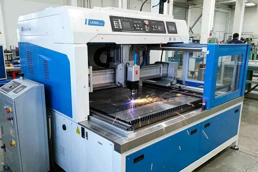
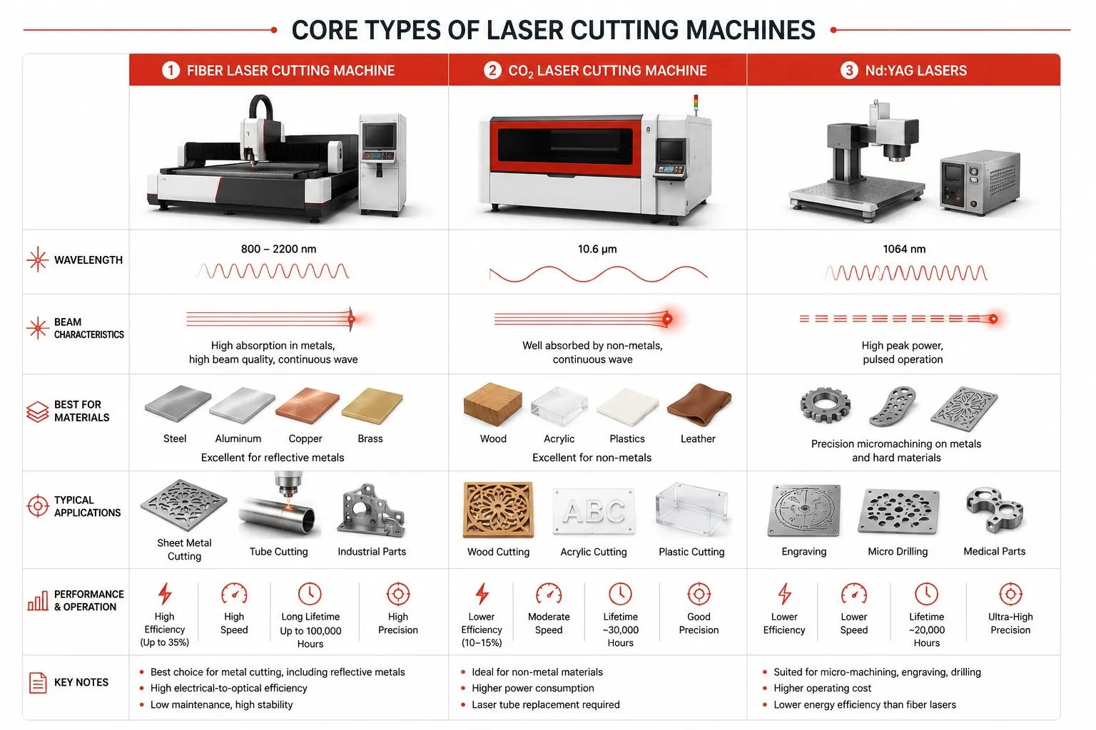
A fibre laser spends most of a machine hour travelling and piercing. Grouping parts by thickness and sharing edges is what turns that hour into cut length.
Piercing and Travel: The Machine-Hour Drivers
Piercing is the least productive second of the cycle. The head stops, the beam burns through the full thickness, and the machine moves nowhere while it happens; on medium-thick plate every closed inner contour pays that cost again. It also leaves a witness: the pierce point is where dross and a slight taper are most likely to appear.
Four rules remove most of it:
- Share an edge instead of closing a loop. Two parts nested along a common line need one cut and no second pierce; a part with a separate closed outline needs both.
- Turn small holes into slots. Below roughly 3 mm diameter, a slot pierces once and cuts a shorter path than a round hole of the same function, and it lets the melt run out.
- Put the pierce point on scrap. A lead-in that starts in the slug rather than on the finished edge keeps the witness mark off the part.
- Take tapping off the bed. A tapped hole forces the machine to stop and the operator to intervene; moving the thread to a secondary operation cuts cycle time on the laser by around 28% on hole-heavy parts.
Ask for the pierce count per part on the quotation. It is the line that explains why two suppliers differ on the same drawing, and it tells you immediately which features are being charged twice. Nitrogen assist at 10–14 bar keeps the kerf stable on stainless and aluminium; below that the cut edge starts to oxidise and the deburring station reappears. A dense perforated panel is the other half of the gas bill: every breakthrough draws assist gas, and the heat that accumulates around the head is what shortens nozzle life first.
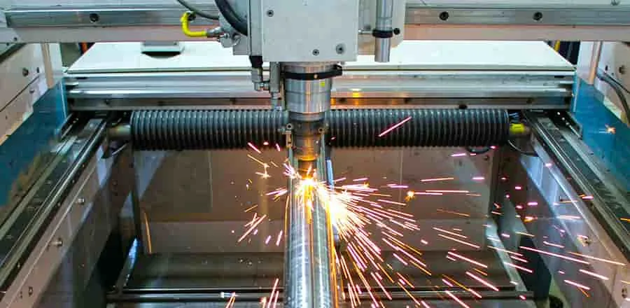
Tube laser cutting: a tubular part pays one pierce per face, and pierce starts reach the quotation the same way they do on a flat sheet.
Nesting and Material Utilisation
Nesting is where a laser cutting quote is won or lost, because the sheet is a fixed cost per kilogram and every unused square metre is paid for either way. Two techniques do the work.
Common-line cutting lets adjacent parts share a single kerf: the shared edge is cut once, so the material between them and half the cut length both disappear. Where the shared line is long and straight, this is the single largest saving on a nested batch. Micro-joints — short 2.0 mm bridges left across the cut — hold the parts in place so a finished piece cannot tip into the bed and interrupt the next contour; they are snapped or trimmed after the sheet comes off.
Where edges are not shared, spacing still matters. A gap of at least 1.5 times the sheet thickness keeps the heat from one cut from distorting its neighbour, and it keeps the head from colliding with a part that has already been freed. Two further habits raise usable area: nest parts that share one long straight silhouette rather than mixing shapes, and group the sheet by thickness so the machine is not re-tuned mid-nest.
Asymmetric parts are the awkward case. Where a part has concave zones, nest it against its own mirror image so that the two fill the gap each one would leave alone; the micro-joint above is the same idea at a smaller scale. It is also worth asking whether a quotation is priced on the net part area or on the gross nest area, because the difference between them is the skeleton — and the answer tells you whose nesting assumptions the price is built on.
Slope tweaks belong on the edges that do not mate. Giving a non-mating edge a few degrees of relief, or opening out an internal cutout that only needs clearance, removes piercing and travel without touching the part's function. Send marked drawings: the nesting engineer can only loosen what the drawing says is free.
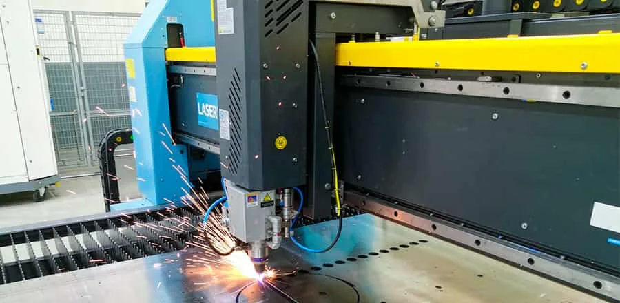
Nesting a circular contour against a shared straight edge: the outer profile is cut once for two parts, and the pierce starts drop with it.
Hole Geometry and the Diameter-to-Thickness Rule
Hole size is a function of sheet thickness before it is anything else. A hole wider than the plate gives the molten metal a path down and away from the cut, which keeps the lens and nozzle clean and leaves a round edge; as the hole narrows the melt has to escape through the kerf itself, and the cut degrades quickly.
- 1.2:1 (hole diameter to thickness) is the working default: stable piercing, no measurable distortion, no special parameters.
- 1.5:1 is reachable with precision-grade piercing — a high-frequency pulse at reduced average power — and leaves no mark on the pattern around it.
- Below 0.8:1 the process is fighting itself: burn-through along the wall, dross on entry, and a real risk of the slug bursting during the pierce.
Dense patterns need web spacing as well as aspect ratio. Leaving at least one sheet thickness of material between neighbouring holes stops the row from heat-soaking, which is where hole-to-hole distortion actually comes from on a perforated panel.
On heavier plate the calculation changes. A 4.0 mm stainless part with a small bore is better premarked with a fibre dot and finished to size in a secondary machining pass than forced through the laser; the position comes from the laser, the diameter and the roundness come from the mill. Material gauge and condition are specified separately (ASTM A480 covers the stainless condition), and a bore that sits outside the laser's stable window is exactly the callout worth discussing before the batch is cut.
Tolerance Bands and the Feed-Rate Trade-Off
Laser cutting has one general band and two special ones. Unless the drawing says otherwise, the general tolerances of ISO 2768-1 apply, and the cut runs at full feed rate with a standard assist gas; the conventional figure for a formed sheet metal part sits around ±0.02 mm on the laser profile. Anything tighter is bought by slowing the machine.
| Grade | Typical band | How it is cut | Where it belongs |
|---|---|---|---|
| Conventional | ±0.02 mm, ISO 2768-1 | full feed rate, standard assist gas | blank outlines, clearance slots, non-mating edges |
| Precision | ±0.008 mm | slowed feed rate, controlled kerf | bores and edges that locate another part |
| Ultra-precision | ±0.004 mm | low-frequency pulse trim, staged passes | press-fit and optical seats, only where the assembly needs it |
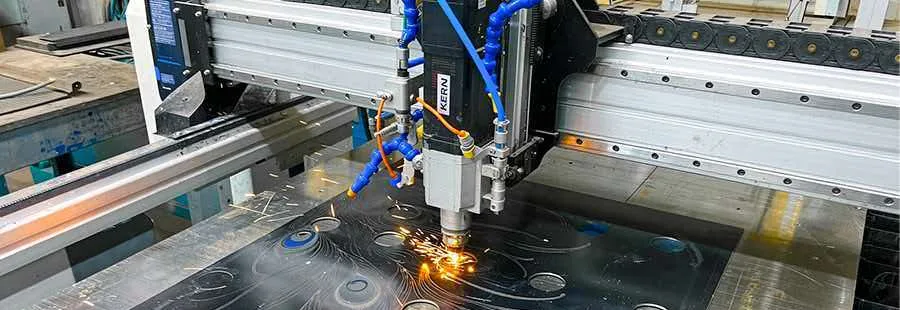
Hole geometry and web spacing decide whether a dense pattern holds its diameter: keep the bore above the plate thickness and at least 1T of web between holes.
The trade-off is steep at the top end. Dropping the pulse frequency far enough to hold ±0.004 mm roughly doubles the price of the part carrying that callout, because the machine spends its time finishing instead of cutting. The practical answer is to grade the drawing: tight callouts on mating bores and datum edges, the general band everywhere else, and ISO 286-1 IT grades used where a linear size genuinely needs a named class. Buyers who grade a drawing instead of tightening it rarely pay for the tight band more than once.
Material, Gauge Consolidation and Assist Gas
Material cost responds to two decisions, neither of which is the alloy itself. The first is the number of gauges in the assembly: one gauge across several parts removes gas swaps and nozzle re-tunes, and buying a standard gauge instead of a special one takes a few per cent off the raw material line before anything is cut. The second is assist gas, which has to match the material rather than the drawing's habit.
- Nitrogen displaces oxygen at the cut line, so stainless and aluminium come off the bed free of oxide scale at about Ra 1.6 µm and go straight to assembly. The gas volume is higher and the cost per part rises, and the treatment that would otherwise remove the scale — pickling, as described in ASTM A380 — comes off the routing.
- Oxygen stays the right choice for mild steel: faster cutting, cheaper gas, at the cost of an oxidised edge that will be finished or painted anyway.
- Reflective grades are a machine-hour derate, not a material problem. Copper, brass and aluminium send part of the beam back up the path, so cutting speed drops by roughly 25% unless the head is set for it; tell us the alloy at RFQ and the derate is priced honestly instead of discovered mid-batch.
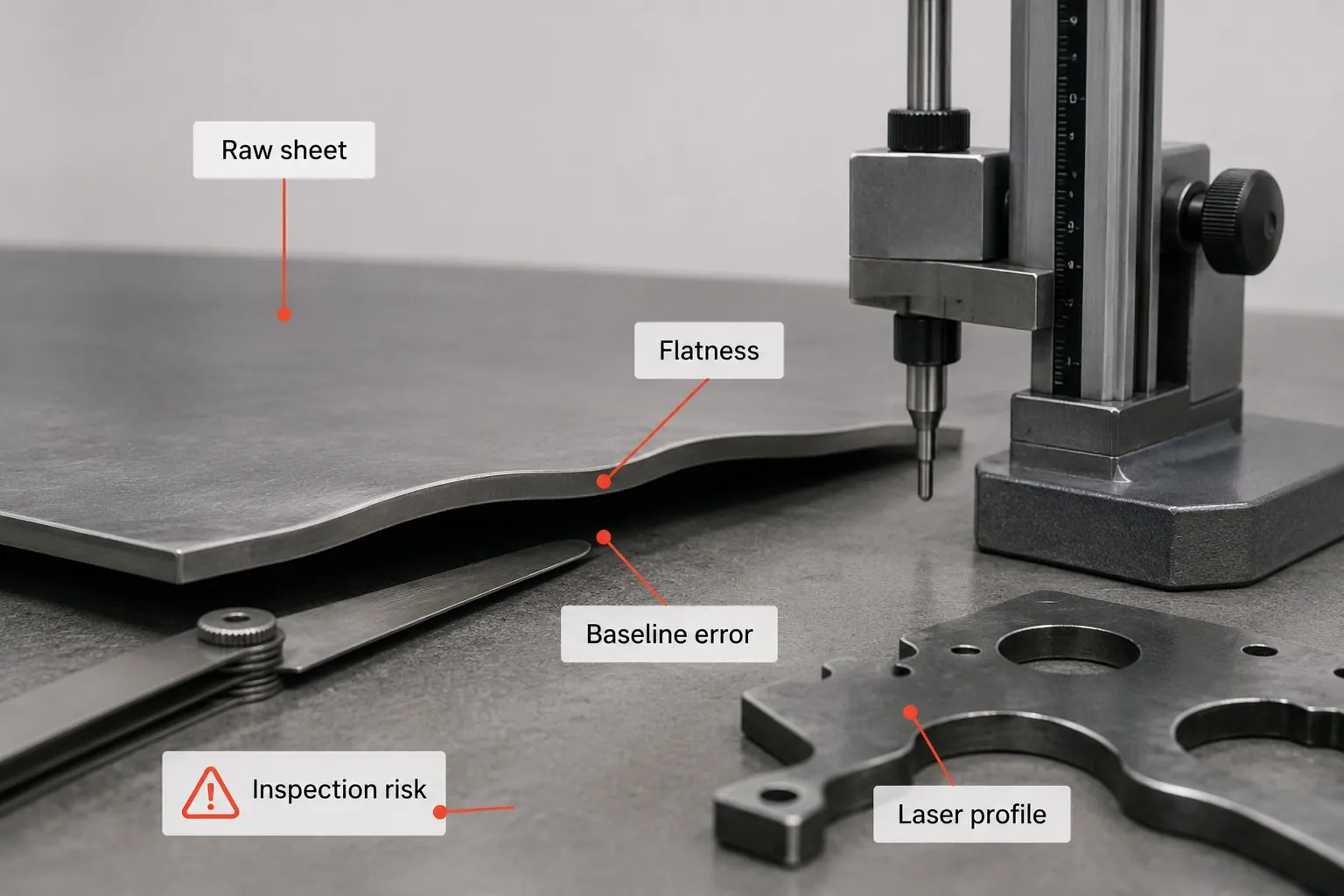
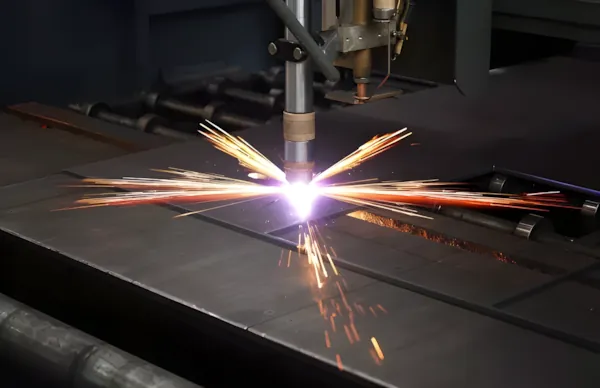
Sheet condition matters as much as grade. Unannealed coil stock carries rolling stress that releases as warp, which lifts the sheet into the nozzle and produces a cut that drifts off the programmed path; where flatness is functional, specify stress-relieved or annealed stock. The same logic explains why thin stainless behaves so badly on a plasma table: the heat-affected zone there is wide enough to buckle the part, while a fibre laser keeps it narrow.
Secondary Operations and the Notes That Prevent Them
Dross removal and deburring are the labour lines that grow quietly. A part cut with nitrogen on stainless arrives clean; the same part cut with oxygen arrives with an oxide edge that has to be treated before paint or weld. Whether that edge needs grinding is graded rather than assumed: cut quality is classified by dross class and perpendicularity in ISO 9013:2017, and the class on the drawing is what should decide if the grinding station is in the routing. The cheapest secondary operation is always the one designed out of the process.
Three drawing notes do most of that work. A burr allowance states which edges may carry a burr and which must be broken. An edge break callout tells the shop whether the edge is functional or cosmetic. A self-locating feature — a tab, a notch or a pair of holes — lets the parts assemble without a fixture. Specify the edge condition and how it will be checked (visual, or measured roughness) and post-processing stops being an assumption somebody has to absorb.
Part consolidation fits here too. A symmetric tab-and-slot design that replaces three separate brackets with one cut part removes two pierces, two nests and an assembly step at the same time — usually the largest single saving available on a sheet metal design, and one that costs nothing but a drawing revision.
Standard Thicknesses and Hardware
Hardware standardisation is invisible in the part and very visible in the price. Every distinct thread form needs its own tap mounted and its own set-up; a single form such as M6 × 1.0 keeps one tap in the machine and delivers all the fasteners in one box. The same principle applies to inserts: standard callouts, standard gauges, fewer tool changes.
Thickness consolidation is the second half. Two gauges across an assembly can share one clamp height, which turns three set-ups into one, and standard stock thicknesses cut materially better than an odd size because the parameters are already proven for them. Blanking datum faces belong to the general band; only the assembly datum faces need the tight one, and a quote should never charge slow finishing time on a face that only positions a blank.
Laser Cutting at SHBD Metal
We have been cutting sheet and tube since 1994 and run fibre laser capacity for both, so the pierce-and-nesting arithmetic in this guide is what our own quotes are built on. The shop works to an ISO 9001:2015 quality system with 150+ staff, more than a hundred machines and seven inspectors, and laser-cut parts are checked against the drawing with CMM reports and first-article documentation when the programme needs them. What we do not claim is a certification we do not hold: if a programme requires a certified automotive quality system from the production supplier — rather than IATF 16949 being mentioned as a nice-to-have — tell us at RFQ stage and we will say plainly whether we fit.
Send the drawing before you need a price. We return the pierce count, the nesting plan and band-by-band tolerance advice with the quotation, so the revision that takes cost out happens before the first sheet is cut rather than after the first batch. Sheet profiles belong to laser cutting, tubular parts to tube laser cutting, and formed or welded assemblies to sheet metal fabrication.
Send the Drawing for a DFM Quote
FAQs
What actually drives the price of a laser-cut part?
Four lines, in this order: pierce count, total cut length, material utilisation, and the finishing labour the edge condition forces. Machine hours are charged as pierce starts plus travel plus cut length, so a contour that has to be pierced and closed costs more than the same outline shared between two parts. Nesting decides how many sheets the batch consumes, and the specification decides whether a deburring or pickling station is on the routing at all. Material price is the one line a buyer usually focuses on first, and it is rarely the largest.
How small a hole can a fiber laser cut cleanly?
Keep the hole diameter at or above the sheet thickness — 1.2:1 is the working rule of thumb, because a hole wider than the plate has somewhere to send the molten metal and the nozzle lens stays clean. Precision-grade piercing with a reduced pulse frequency reaches about 1.5:1 on stainless and aluminium, and the top of a dense pattern stays unmarked. Below 0.8:1 the melt has nowhere to go: burn-through, dross and occasional burst risk. Where the design needs a cluster of holes below 3 mm, slots usually cut faster and cleaner than round holes.
Does a tighter tolerance always cost more?
Yes, and the mechanism is feed rate rather than material. Precision laser cutting tolerances are held by slowing the cut and controlling the kerf, and an ultra-precision band around ±0.004 mm needs a low-frequency pulse trim that can double the price of the part carrying it. That is why the callout belongs only where a mating condition exists — bore diameters, locating edges, a press-fit seat — while outlines, clearance slots and non-mating edges take the general band from ISO 2768-1, with ISO 286-1 IT grades covering the linear sizes in between.
Is nitrogen assist gas worth the extra cost?
It depends on what happens after the cut. Nitrogen displaces oxygen at the cut line, so stainless and aluminium come off the bed oxide-free at around Ra 1.6 µm and go straight to assembly, where oxygen cutting would have sent them to pickling first (the treatment described in ASTM A380). The gas volume is higher and the cost per piece rises, so oxygen remains the right choice for mild steel parts that will be finished anyway.
How do I get a lower price on the next repeat order?
Freeze the choices that drive setup: one gauge across the assembly, one thread form, standard thicknesses instead of special ones, and common-line nesting for parts that share a straight edge. Send marked drawings so the nesting engineer knows which edges are as-drawn and which can be slope-tweaked, and group the batch by thickness so the machine is not re-tuned between parts. On a repeat order the tolerance plan should already be settled, so only the quantities are re-quoted.
Summary
Laser cutting cost is decided by three drawing-level choices: how many times the beam has to pierce, how tightly the parts share the sheet, and how tight the callouts are on faces that never mate. Fix those and the quotation moves without changing the alloy or the machine. Keep the tolerance plan graded, keep the gauges and thread forms standard, and put the edge condition on the drawing where the shop can see it.
Comment
0 comments
Got thoughts or experiences to share? We’d love to hear from you!