Determining if a design exceeds standard laser cutting limits without having a formal quote in hand stalls engineering workflows. Guessing whether a 15mm carbon steel plate requires a 6kW or 10kW fiber laser often leads to rejected designs, unexpected tooling fees, or edge quality failures during production. We analyzed thousands of rapid prototyping and mass production runs to standardize the exact power-to-thickness ratios for both fiber and CO2 systems. For mechanical engineers and procurement teams evaluating equipment capabilities or outsourcing feasibility, the data below eliminates the guesswork. Here is the comprehensive laser cutting thickness chart to benchmark your next project.
The Core Laser Cutting Thickness Charts
Fiber Laser Cutting Thickness Chart (Metals)
Fiber lasers rely on a solid-state gain medium to produce a highly focused beam, making them the standard for processing sheet metal. Different metals have varying reflectivity, thermal conductivity, and melting points. These physical properties directly impact the required wattage for clean cuts.
This fiber laser cutting thickness chart outlines the absolute maximum thickness limits for common metals based on the laser’s power output.
| Material | 500W | 1000W | 1500W | 2000W | 3000W | 6000W | 8000W | 10000W | 12000W | Absolute Max Cut Thickness |
| Aluminum | 1–2 mm | 2–3 mm | 3–5 mm | 5–8 mm | 8–12 mm | 12–20 mm | 20–25 mm | 25–35 mm | 25–35 mm | 35 mm |
| Stainless Steel | 1–3 mm | 3–5 mm | 5–6 mm | 6–8 mm | 8–12 mm | 12–20 mm | 20–25 mm | 20–25 mm | 20–25 mm | 40 mm |
| Brass | 1–2 mm | 2–3 mm | 3–5 mm | 5–6 mm | 6–8 mm | 8–12 mm | 12–14 mm | 12–14 mm | 12–14 mm | 14 mm |
| Carbon Steel | 1–6 mm | 6–12 mm | 12–14 mm | 14–18 mm | 18–22 mm | 22–25 mm | 22–25 mm | 22–25 mm | 22–25 mm | 25 mm |
Pro Tip: Carbon steel is a corrosive material and consumes more laser power than non-corrosive metals at an equal thickness. When looking at a fiber laser cutting thickness chart stainless steel 1500w 2000w 3000w, note that stainless limits out slightly lower than mild steel at those mid-range wattages. Aluminum and brass feature high reflectivity and require more power than steel for an identical thickness.
Cutting speed has an inverse correlation with thickness. Thick materials require reduced feed speeds for full penetration, while thin sheets run fast to boost throughput without quality loss. The following fiber laser cutting speed chart steel thickness data highlights optimal baseline speeds.
| Material | 500W | 1000W | 1500W | 2000W | 3000W | 6000W | 8000W | 10000W | Peak Speed |
| Aluminum | 4–5.5 | 6–10 | 10–20 | 15–25 | 25–38 | 45–55 | 55–65 | 60–75 | 85 m/min |
| Stainless Steel | 8–13 | 18–25 | 20–27 | 24–30 | 30–35 | 45–55 | 55–66 | 60–75 | 85 m/min |
| Brass | 4–5.5 | 6–10 | 8–13 | 10–16 | 20–35 | 45–55 | 55–65 | 65–75 | 85 m/min |
| Carbon Steel | 7–9 | 8–10 | 15–26 | 24–30 | 30–40 | 35–42 | 35–42 | 35–42 | 42 m/min |
If you are plotting a fiber laser cutting speed chart mild steel 1mm thickness, the machine will operate near the peak speed limit for the specific wattage. A laser cutting speed chart 3kw steel thickness profile will sit comfortably at 30 to 40 meters per minute for thinner gauges.
CO2 Laser Cutting Thickness Chart (Non-Metals)
CO2 lasers operate at a 10.6μm infrared wavelength. This wavelength is optimized for non-metals with high light absorption rates. A reliable co2 laser engraver cutting thickness chart depends heavily on whether you are using a desktop unit or an industrial machine.
Low & Medium Power (40W–100W)
| Material | 40W | 50W | 60W | 80W | 100W |
| Acrylic | 3 mm | 5 mm | 5–8 mm | 6–10 mm | 10–12 mm |
| MDF | 1 mm | 2 mm | 4 mm | 5 mm | 6 mm |
| Plywood | 3 mm | 5 mm | 8 mm | 10 mm | 13 mm |
| PVC | 2 mm | 3 mm | 4 mm | 5 mm | 8 mm |
High Industrial Power (130W–300W)
Higher power enables thicker cutting or significantly faster cutting speeds for the same thickness.
| Material | 130W | 150W | 180W | 220W | 300W |
| Acrylic | 12–25 mm | 17–28 mm | 20–30 mm | 20–35 mm | 20–40 mm |
| MDF | 8 mm | 10 mm | 10 mm | 12 mm | 18 mm |
| Plywood | 15 mm | 15 mm | N/A | N/A | N/A |
Excessively fast speeds cause incomplete cuts on these machines. Conversely, overly slow speeds lead to overheating, charring, and material deformation.
Key Factors Affecting Laser Cutting Thickness and Speed
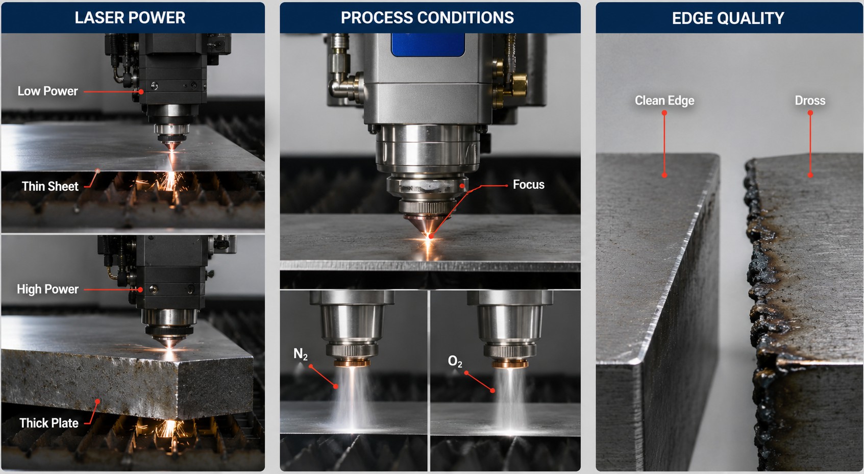
Laser Power and Capacity
Power is the most decisive factor for any laser cutting thickness and speed chart. Low-power units strictly handle thin sheets. High-power generators manage thick workpieces and maintain high cutting speeds.
Auxiliary Process Conditions
Variables like lens focal length and assist gas pressure heavily impact your actual cutting capacity. Nitrogen is typically used for stainless steel and aluminum to prevent oxidation, while oxygen is used for carbon steel to drive an exothermic reaction that aids the cut. Machine frame stability and the physical quality of the laser tube also dictate edge finish.
Edge Quality Considerations
There is a distinct difference between severing a part and achieving a precise, clean edge. Pushing a machine to its absolute maximum limit in a laser cutting tolerance chart by thickness steel often results in increased dross and thermal distortion. Improper speed adjustments create rough edges, burn marks, or uncut gaps.
Procurement and DFM Strategies for Laser Cut Parts
Engineers and buyers must balance lead times, quality, and pricing when sourcing laser-cut components. RapidDirect provides automated quoting and Design for Manufacturability (DFM) analysis to help control costs while ensuring quality, significantly shortening project cycles.
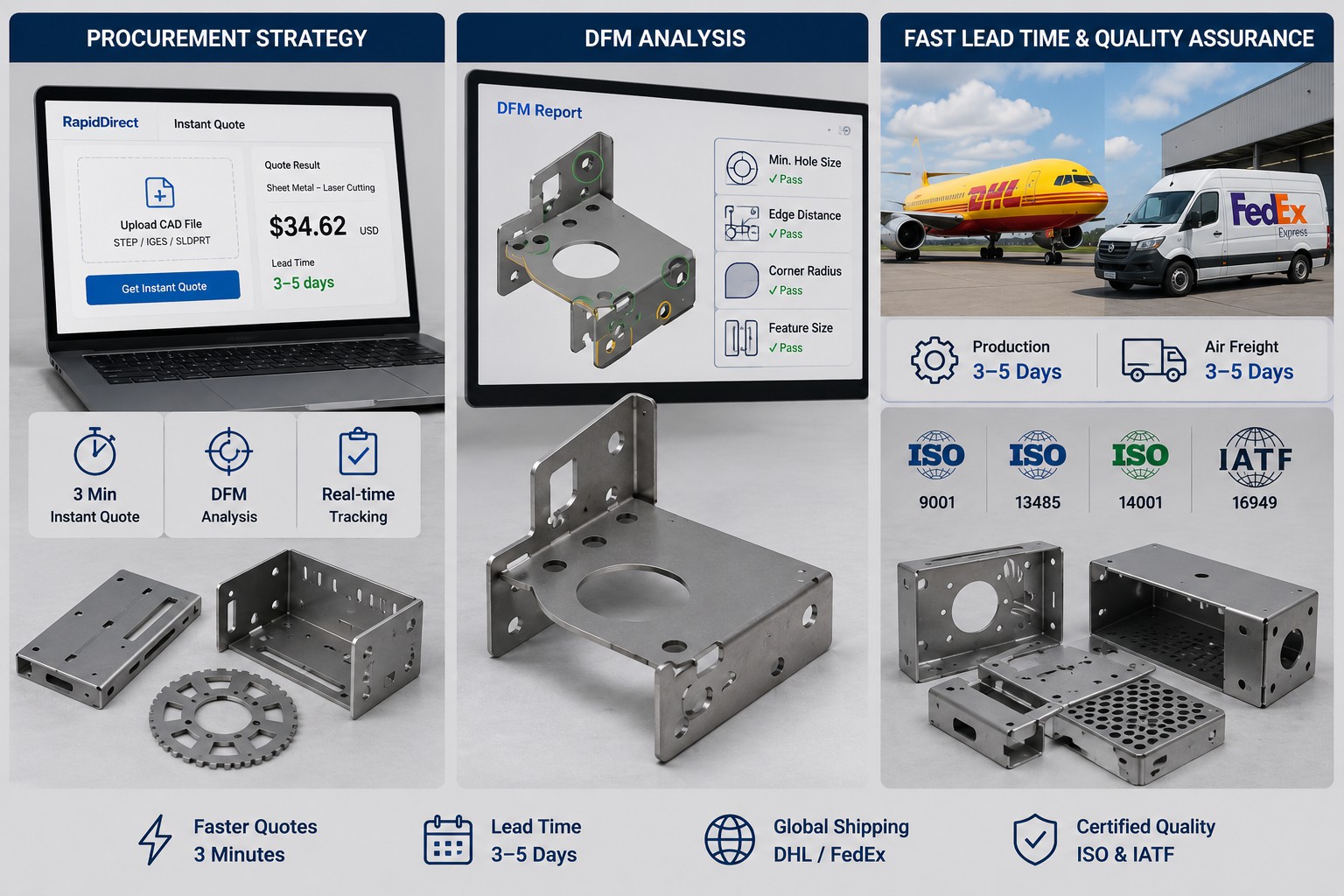
Customers are usually working with two to three options for these services. RapidDirect wins because our quotes are faster, returning instant prices in 3 minutes compared to the 1 to 2 days required by competitors. You can upload your CAD file directly to our intelligent online platform for real-time order tracking and free DFM reports. This prevents parts from failing manufacturability checks later in the process.
Our prototyping standard lead times are 3 to 5 days. We support this with global air freight through DHL and FedEx, which typically takes 3 to 5 days. RapidDirect holds ISO 9001, 13485, 14001, and IATF 16949 certifications, ensuring a robust quality system for your components.
Summary of Laser Cutting Thickness
Laser power is positively correlated with maximum cut thickness, while cutting speed shares an inverse relationship with material thickness. Metal and non-metal systems rely on completely independent parameter sets due to physical property gaps. Balancing power, thickness, and speed is critical to maximize edge precision, yield rates, and production efficiency.
Ready to bypass the guesswork? Upload your STEP file to RapidDirect’s platform today for an instant quote and automated DFM feedback.
Laser Cutting Thickness Chart FAQs
Maximum thickness is determined by combined factors including laser power, material properties, and the machine’s overall configuration. Manufacturer official charts provide the most accurate baseline for your specific equipment.
There is no universal fixed value for ultra-thin sheets. A lower-wattage fiber laser is highly capable of slicing 0.2 mm steel at exceptional speeds. Cross-check your metal thickness charts and consult equipment suppliers for tailored parameter settings to prevent warping.
Evaluate four critical factors: your most common cutting materials, the maximum plate thickness you require, the necessary cutting speed or output volume, and your overall budget. Screen those variables against a validated thickness reference chart to pinpoint the required kilowatt rating.
Yes. Cutting too fast on thick materials creates a wider kerf and rougher edge quality, throwing off the final dimensions. Slowing down the feed rate ensures a straighter cut line with less thermal deflection on thick stock.