A CAD model is dimensionally perfect. A printed part is not. The difference between the two is tolerance — and every 3D printing technology answers that question differently.
For engineers designing mating parts, snap fits, bearing seats, or threaded connections, tolerance is the variable that decides whether an assembly works on the first try or needs a reprint. This guide breaks down the real tolerance ranges for FDM, SLA, SLS, MJF, and SLM, and gives you the clearance values and design rules to get parts that fit.
What Are Tolerances in 3D Printing?
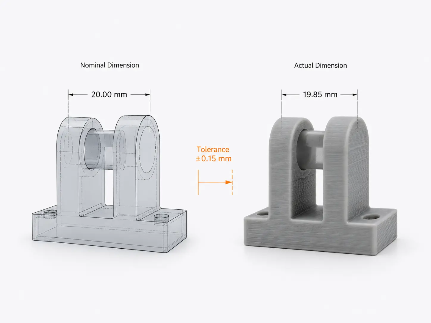
A tolerance is the permissible deviation between the nominal dimension in the CAD file and the measured dimension on the printed part. It is written as ±X mm or ±X%. A part designed at 20.00 mm with a tolerance of ±0.20 mm will measure anywhere from 19.80 mm to 20.20 mm — and still be considered in spec.
3D printing tolerances differ from CNC machining tolerances because of how the part is built. CNC removes material from a solid block with a cutting tool that holds position to microns. 3D printing builds the part layer by layer from molten plastic, cured resin, or sintered powder.
Each layer introduces a small quantization error, and the material shrinks as it cools or cures. The result is a tolerance range that changes with the technology, material, and geometry — not a single number.
3D Printing Tolerance by Technology
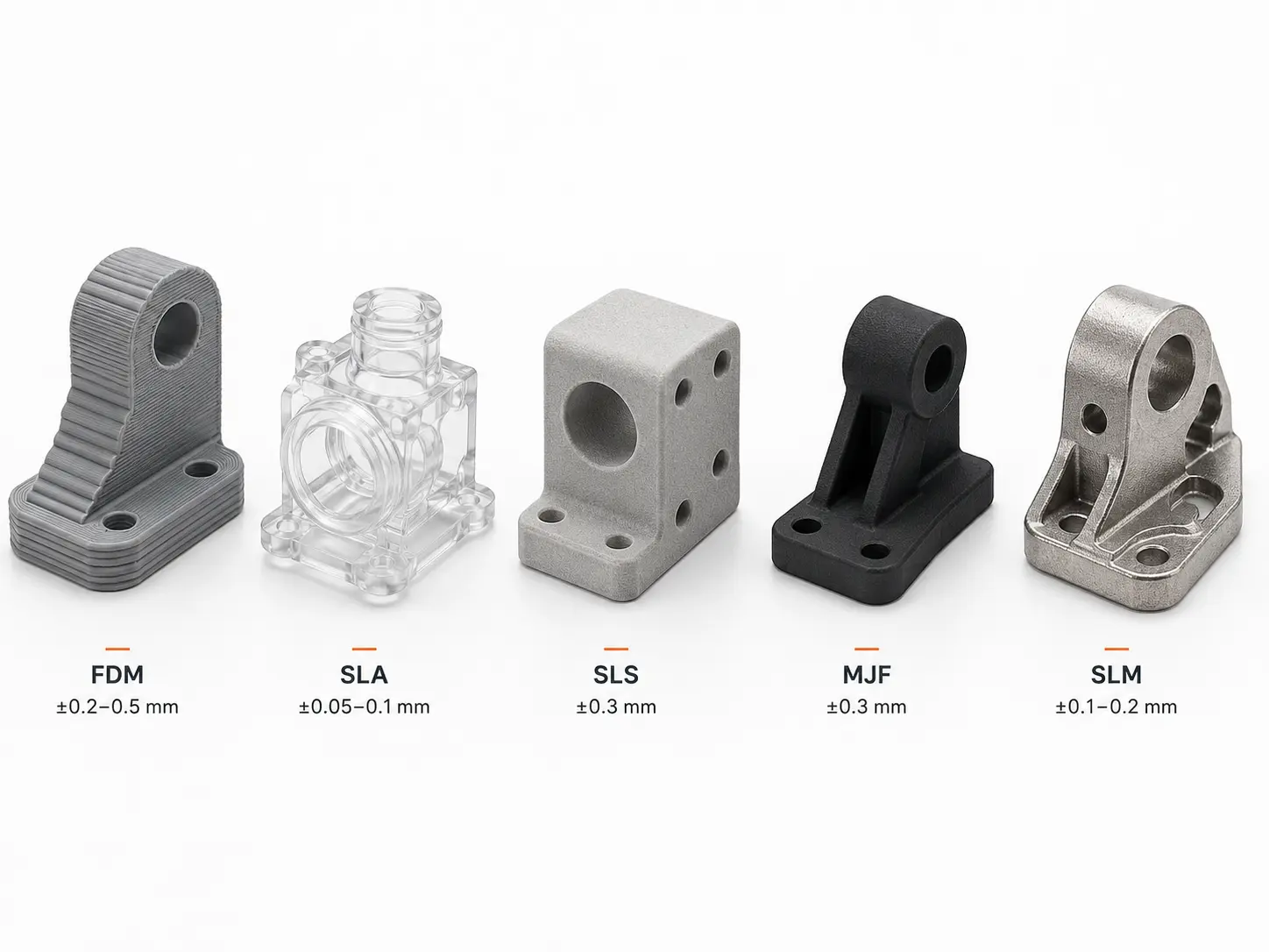
Each 3D printing process operates on a different physical principle, and that principle sets its accuracy ceiling. Below are the tolerance ranges for the five most common technologies used in professional manufacturing.
FDM (Fused Deposition Modeling)
FDM extrudes molten thermoplastic through a heated nozzle, drawing each layer as a bead roughly 0.4 mm wide. The nozzle positions accurately, but the bead swells on exit, shrinks as it cools, and creates visible layer steps.
| Parameter | Typical Range |
| X/Y axis tolerance | ±0.2–0.5 mm |
| Z axis tolerance | ±0.1–0.3 mm |
| Minimum wall thickness | 0.8–1.2 mm |
| Layer height | 0.1–0.3 mm |
| Material shrinkage | 0.3–1.5% |
PLA is the most dimensionally stable FDM material, shrinking roughly 0.2–0.3%. ABS shrinks 0.8–2%, and its higher printing temperature makes warping more likely. A well-calibrated professional FDM machine can hold ±0.1 mm on smaller features; a desktop printer operating without enclosure or flow calibration will sit closer to ±0.5 mm.
SLA (Stereolithography)
SLA cures liquid photopolymer resin with a UV laser. The laser spot is much finer than an FDM nozzle, producing significantly tighter tolerances and a smooth surface finish.
| Parameter | Typical Range |
| X/Y axis tolerance | ±0.05–0.1 mm |
| Z axis tolerance | ±0.05 mm |
| Minimum wall thickness | 0.3–0.5 mm |
| Layer height | 0.025–0.1 mm |
| Resin shrinkage | 0.1–0.5% |
SLA is the most accurate plastic 3D printing technology available at production scale. It suits dental models, jewelry casting patterns, and fine mechanical parts where surface detail and fit matter. Standard resins are more brittle than FDM thermoplastics, so the precision comes with a trade-off in impact resistance.
SLS (Selective Laser Sintering)
SLS sinters nylon powder (typically PA12) layer by layer with a laser. The unfused powder acts as a support structure, so SLS parts can have complex internal geometries without the support-removal marks left by FDM or SLA.
| Parameter | Typical Range |
| General tolerance | ±0.3 mm or ±0.3% (whichever is greater) |
| Minimum wall thickness | 0.7–1.0 mm |
| Layer height | 0.1–0.12 mm |
| PA12 shrinkage | ~3% |
The tolerance as a percentage means a 100 mm part can vary by ±0.3 mm, while a 300 mm part can vary by ±0.9 mm. SLS parts have a finely grained surface and consistent mechanical properties. The material — nylon — is tougher than SLA resin and more temperature-resistant than standard FDM filaments.
MJF (Multi Jet Fusion)
MJF also uses nylon powder (PA12 or PA11) but fuses it with an infrared heating element after selectively applying a fusing agent. The process is faster than SLS and produces parts with more uniform mechanical properties in all directions.
| Parameter | Typical Range |
| General tolerance | ±0.3 mm for the first 25 mm, then ±0.1% of nominal |
| Minimum wall thickness | 0.8 mm |
| Layer height | 0.08 mm |
| PA12 shrinkage | ~2–3% |
MJF is often the better choice over SLS when a project needs higher throughput or more isotropic strength. The tolerance range is comparable to SLS for most part sizes.
SLM (Selective Laser Melting — Metal 3D Printing)
SLM fully melts metal powder (aluminum, stainless steel, titanium, Inconel) with a high-power laser. The process generates significant thermal stress, which distorts the part during printing and requires stress relief after the build.
| Parameter | Typical Range |
| As-printed tolerance | ±0.1–0.2 mm |
| Minimum wall thickness | 0.3–0.5 mm |
| Layer height | 0.03–0.05 mm |
SLM can produce complex metal geometries that would be impossible to machine from a solid block, but the as-printed tolerance is rarely the final tolerance. Critical bores, mating surfaces, and threads almost always need post-machining on a CNC mill to bring them into spec.
What Affects the Tolerance of 3D Printing?
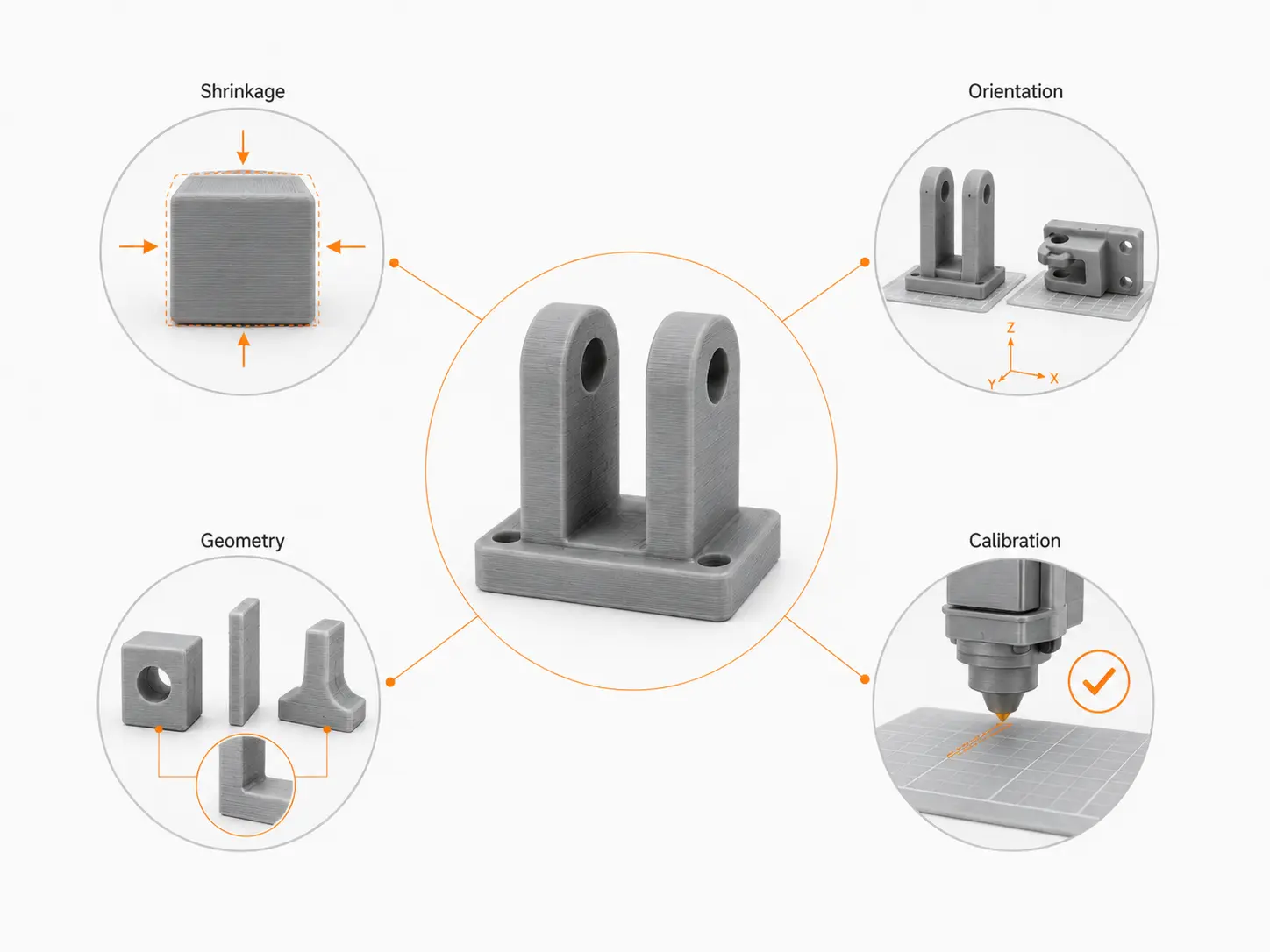
A machine’s rated accuracy is only part of the picture. Four factors push a printed part further from its CAD dimensions, and they compound with part size.
Material Shrinkage
Every material contracts as it cools from its processing temperature. PLA shrinks the least (0.2–0.3%); PETG shrinks 0.5–0.8%; ABS can shrink up to 2%. Nylon (PA12) shrinks roughly 3%, which is why SLS and MJF tolerance specs are often stated as a percentage of the part dimension rather than a fixed value.
Shrinkage error scales with part size. A 10 mm boss loses 0.02 mm to PLA shrinkage — negligible. A 200 mm enclosure loses 0.4 mm — enough to throw off mounting holes.
Print Orientation
Z-axis accuracy is worse than X/Y accuracy in every layer-based technology. The Z dimension is quantized to the layer height, and each layer introduces a small positioning error. For FDM, Z tolerance is ±0.1–0.3 mm; for SLA, roughly ±0.05 mm.
Rule of thumb: orient critical dimensions in the X/Y plane. Shaft diameters run parallel to the build plate; hole depths run perpendicular. Horizontal holes printed parallel to the bed sag at the top and print as slight ovals. Vertical holes print rounder and more accurately.
Part Geometry
FDM-printed holes consistently measure 0.1–0.3 mm smaller than modeled. The extruded bead swells outward from the nozzle path — on an outer perimeter that adds material to the outside of the part; on an inner perimeter it adds material toward the center of the hole. Model holes 0.2 mm oversize as a starting point, and verify with a test print.
The first layer — pressed into the bed for adhesion — splays outward by 0.1–0.3 mm. This “elephant’s foot” widens the bottom 0.5 mm of every part and will jam any fit located at the base. A 0.5 mm chamfer on the bottom edge of mating features eliminates the interference.
Printer Calibration and Process Control
Two printers running the same G-code can produce parts with different tolerances. A professionally maintained machine with per-filament flow calibration, consistent chamber temperature, and regular nozzle replacement will hold the tight end of the tolerance range. A machine without these controls will drift to the loose end.
Clearance and Fit Design Guidelines
The printed part will never match the CAD model exactly. That means two parts modeled to touch will not fit — clearance must be designed in.
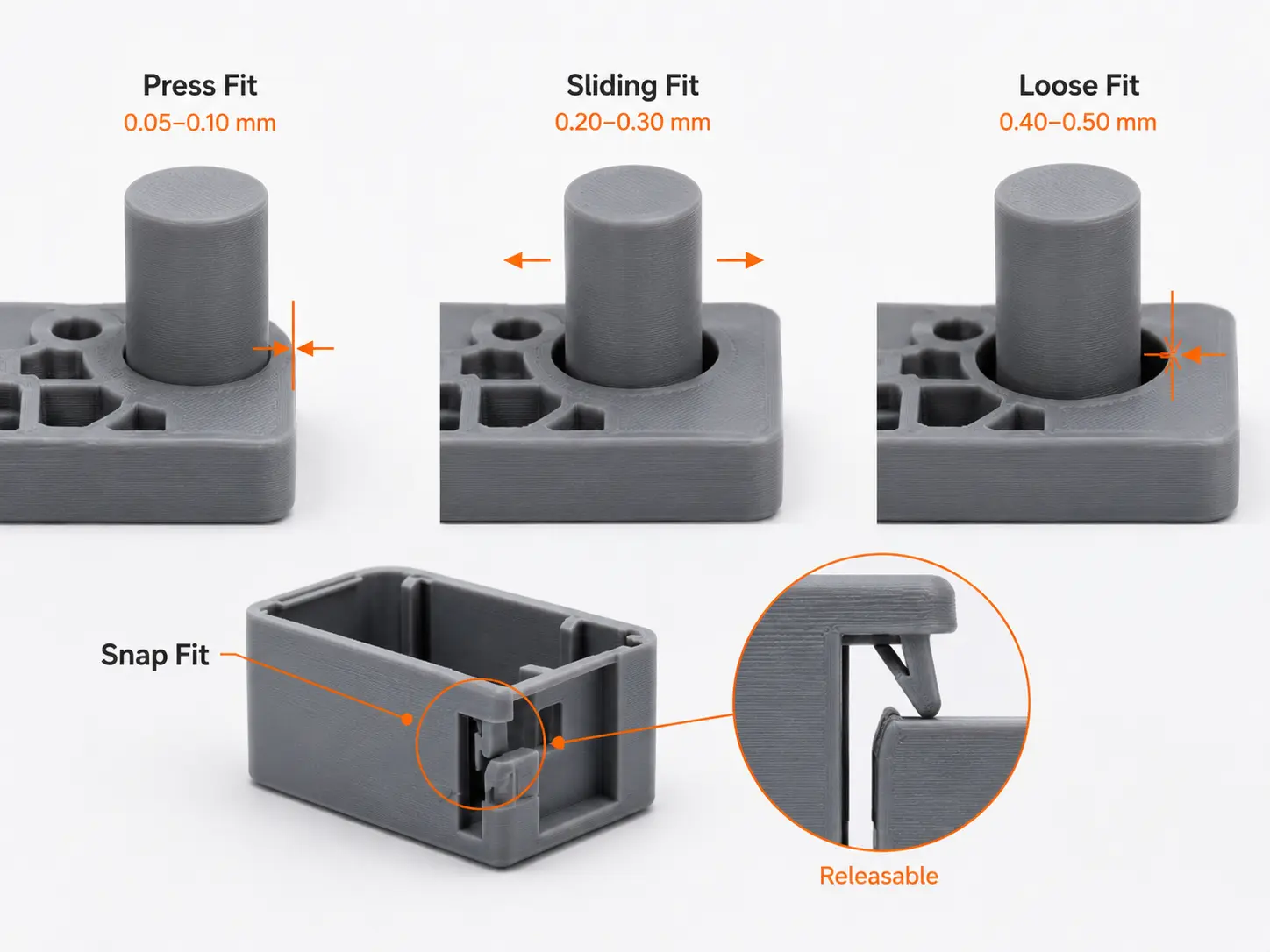
The following values assume FDM with PLA at ±0.2 mm tolerance. Reduce clearances by roughly 30% for SLA; keep them the same for MJF and SLS.
| Fit Type | Clearance per Side | Behavior | Typical Use |
| Press fit | 0.05–0.10 mm | Requires firm push; stays put | Bearings, dowel pins, magnets |
| Sliding fit | 0.20–0.30 mm | Smooth motion, minimal play | Lids, drawers, telescoping parts |
| Loose fit | 0.40–0.50 mm | Falls together freely | Hinges, hooks, chain links |
| Printed threads | 0.20–0.40 mm offset | Threads by hand after one turn | M8 and larger fasteners |
| Snap fit | 0.30 mm + flexure | Clicks in, releasable | Enclosure clips, battery doors |
Place all clearance on one side of the fit — oversize the hole, leave the peg at nominal. Chamfer every insertion edge 0.5 mm so parts self-align during assembly.
Snap fits need a cantilever printed flat on the bed so layer lines run along the beam rather than across it. A typical cantilever is 4–6 mm wide, 1.5–2 mm thick, with a hook depth of roughly 1.5 mm. Print the flexure in PLA or PETG; ABS snap fits fatigue faster under repeated use.
For threaded connections below M8, the 0.4 mm nozzle cannot resolve the thread form cleanly. Use heat-set brass inserts instead. Print the hole 0.2 mm undersize relative to the insert’s outer diameter, press it in with a soldering iron at the material’s softening temperature, and the plastic will flow into the insert’s knurling for a strong, reusable thread.
Test Before You Commit
Printing a tolerance test coupon costs a few grams of material and tells you exactly what clearance your geometry needs. A simple plate with five holes offset from your pin diameter by 0.0, 0.1, 0.2, 0.3, and 0.4 mm will identify the tightest fit your machine and material can hold.
Working with a Manufacturing Supplier — What to Specify
When ordering 3D printed parts from a service provider, the way you communicate tolerance requirements determines whether the parts arrive fit for purpose or need a reprint.
Call out critical dimensions. A part with 50 features may only have three that actually determine fit. Mark those explicitly — a note on the drawing or a comment field in the quoting platform is enough. Suppliers apply standard tolerances globally unless instructed otherwise.
Provide a 2D drawing with GD&T callouts for tight features. The 3D model defines nominal geometry; the drawing defines what deviation is acceptable and what is not. A positional tolerance on a hole pattern or a flatness callout on a sealing surface eliminates ambiguity that a STEP file alone cannot resolve.
Use the DFM report. Many manufacturing platforms, including RapidDirect, generate a free DFM analysis as part of quoting. The report flags thin walls, trapped volumes, unsupported overhangs, and features likely to drift outside tolerance. Reviewing it before approving production catches dimension problems before material goes down.
Request first article inspection (FAI) for production runs. For orders above prototyping quantities, ask the supplier to measure critical dimensions on the first part and share the data. If the first article is in spec, the batch is likely in spec. If it is out, the process gets corrected before the rest of the order runs.
When 3D Printing Tolerances Aren’t Enough
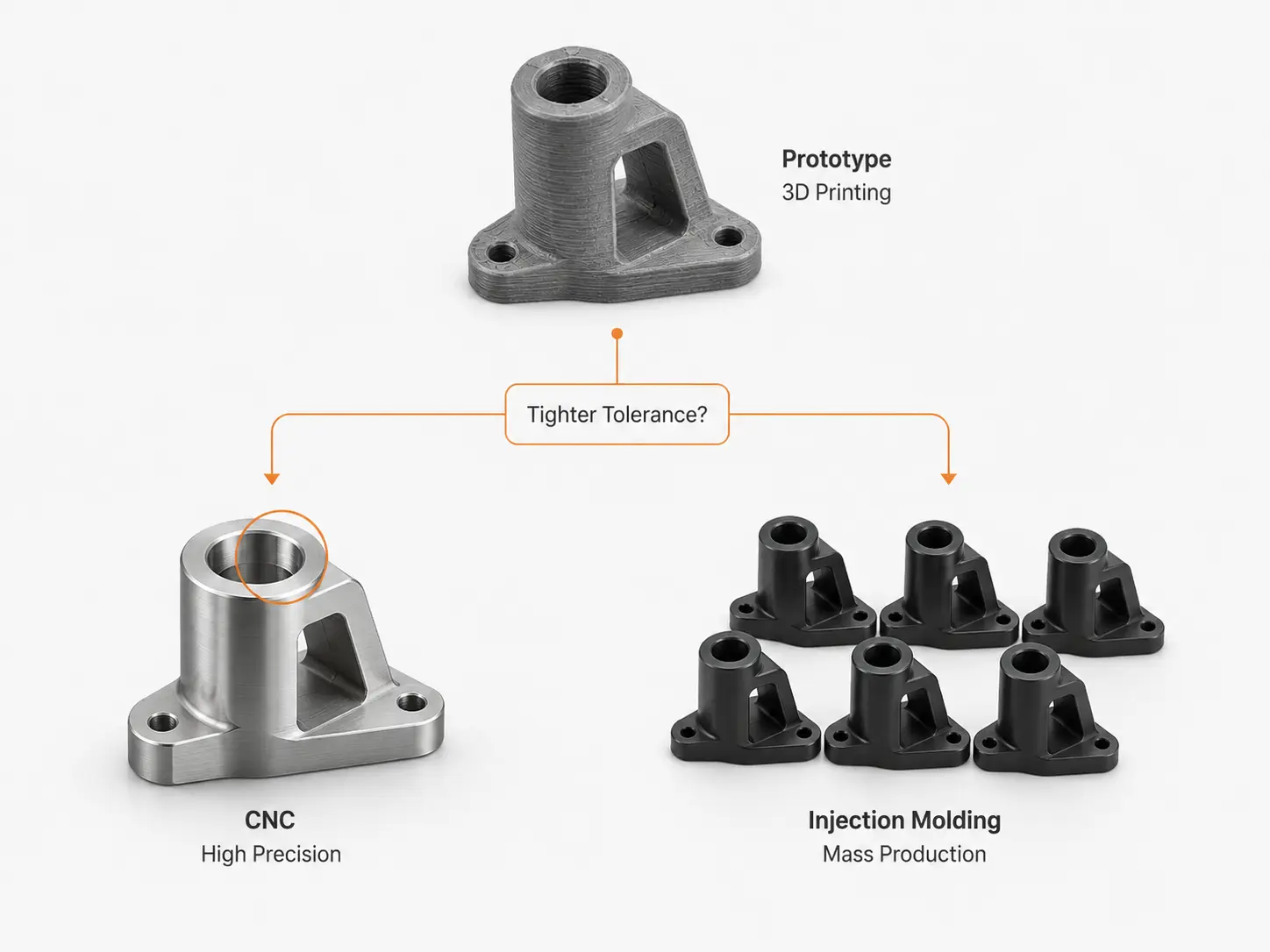
Tolerances tighter than ±0.05 mm are outside the practical range of polymer 3D printing — even SLA. When a project demands that level of precision, three paths are available.
Post-process critical features. Drilling, reaming, and tapping bring individual holes to exact diameters. Annealing stabilizes nylon and ABS dimensions by relieving internal stress before final machining. These steps add cost and lead time but keep the design mostly within the 3D printing workflow.
Switch to CNC machining. CNC can hold ±0.01 mm on metals and engineering plastics, with surface finishes that 3D printing cannot match and fully dense material properties with no porosity or anisotropy. If the project requires bearing bores, sealing surfaces, tight dowel pin fits, or flatness specifications, CNC machining is the more reliable route.
A hybrid approach often makes sense: 3D print the complex body geometry, then machine only the critical mating surfaces. This combines 3D printing’s geometric freedom with CNC’s precision where it matters.
Move to injection molding for production scaling. Once the design passes prototype validation and moves toward volume production, injection molding provides repeatable tolerances (±0.05 mm on well-designed steel tools) at a much lower per-part cost.
Conclusion
3D printing tolerance is not one number — it is a function of technology, material, part geometry, and process control. FDM delivers ±0.2–0.5 mm, enough for most functional prototypes and enclosures. SLA tightens that to ±0.05–0.1 mm for fine mechanical parts and visual models. SLS and MJF sit at ±0.3 mm with the advantage of support-free complex geometries. SLM can produce metal parts within ±0.1–0.2 mm, but critical features typically need post-machining after the build.
Design clearance into every mating interface. Start with the values in this guide, print a test coupon, and measure. The cost of a 5-gram verification plate is almost always lower than the cost of a reprint.
If the tolerances still need to be validated before committing to a full build, you can upload the CAD file through RapidDirect Platform to get a free DFM check and an instant 3D printing quote. For parts requiring tighter precision than 3D printing can hold, CNC machining service is also available within the same platform.
FAQ
There is no single standard — it varies by technology. FDM holds ±0.2–0.5 mm, SLA holds ±0.05–0.1 mm, and SLS/MJF hold roughly ±0.3 mm or ±0.3% of the part dimension. The standard you design depends on the process you are using.
SLA achieves the tightest tolerances among polymer 3D printing technologies, at ±0.05–0.10 mm in X/Y and ±0.05 mm in Z. It is the preferred choice for dental models, jewelry casting, and small mechanical parts where fit and surface finish are critical.
Print a test plate with a series of holes or slots offset from a known pin or key dimension — for example, a 20 mm peg and holes at 20.0, 20.1, 20.2, 20.3, and 20.4 mm. Find the smallest hole that accepts the peg without force. That is your minimum clearance. Run the test on the same material and machine you will use for the production part.
For FDM in PLA or PETG: 0.05–0.10 mm per side for a press fit, 0.20–0.30 mm for a sliding fit, and 0.40–0.50 mm for a loose fit. Reduce these values by about 30% for SLA. Always test with a coupon before printing the full assembly.
Ask for a first article inspection (FAI) report on a sample print before committing to a production run. If the supplier provides process capability data for their machines, that gives a statistical view of tolerance consistency across batches. A test coupon printed in your material and orientation is the fastest way to confirm fit before the full order runs.