
Precision sheet metal forming is not about owning the newest press brake. It is about controlling seven variables that determine whether a batch of 500 brackets all come out within tolerance — or whether every third part needs rework.
Most shops can bend metal. The gap between “bent” and “bent to spec, batch after batch” lives in process control: how material is selected, the flat pattern calculated, springback compensated, and inspection closed.
These seven practices target the decisions that directly affect formed-part accuracy.
1. Apply DFM Rules for Bend Relief and Feature Placement
A correct flat pattern does not guarantee a formable part. Two DFM rules prevent the most common precision-killing errors before the first bend.
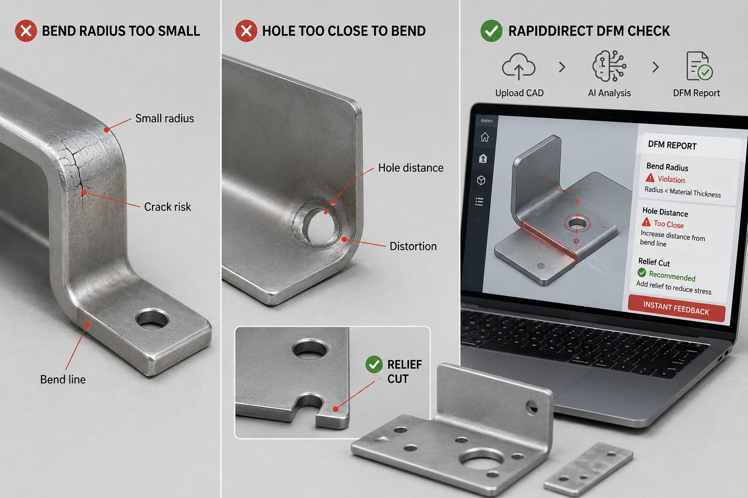
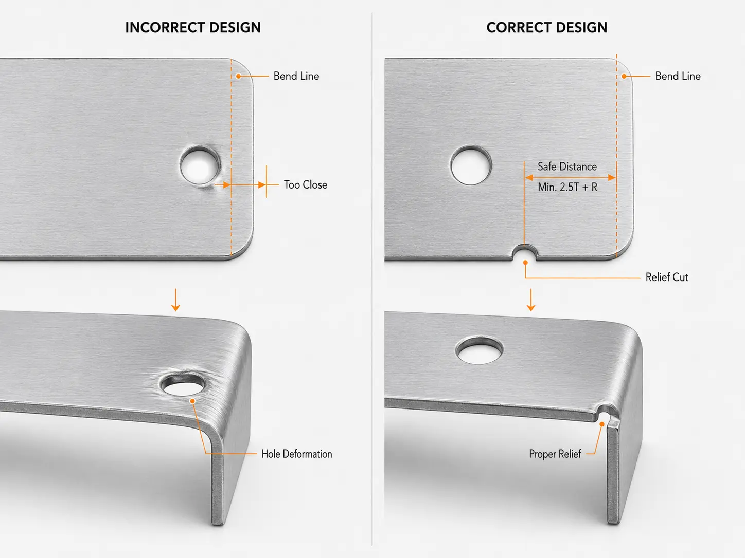
Hole-to-bend spacing. Place holes at least 2.5 × material thickness plus the inside bend radius from the start of any bend. For holes larger than 25 mm, increase that distance. A hole placed too close to a bend line ovals, tears, or shifts position. If a hole must sit inside that safety zone, drill or punch it after bending.
Bend relief. Where two bends intersect, cut a relief notch. Width ≥ material thickness, depth ≥ bend radius + material thickness. Without relief, material bunches at the corner, creating an uncontrolled bulge that throws off adjacent feature positions.
| Rule | Minimum | Applies To |
| Hole-to-bend spacing | 2.5T + R | Holes < 25 mm diameter |
| Large-hole-to-bend spacing | 2.5T + R (verify) | Holes ≥ 25 mm diameter |
| Bend relief width | ≥ T | All intersecting bends |
| Bend relief depth | ≥ R + T | All intersecting bends |
T = material thickness, R = inside bend radius
These checks take seconds in CAD and prevent hours of rework on the shop floor. An automated DFM review from suppliers can catch the same issues before the file reaches the press brake, flagging hole-to-bend conflicts and missing reliefs before production starts.
2. Select the Right Material and Account for Grain Direction
Material choice sets the floor and ceiling for achievable precision. Every alloy has a bend radius limit — tighter than the minimum, and the outer surface cracks.
| Material | Typical Minimum Inside Radius |
| Mild steel (A36, 1018) | 1T |
| Stainless steel 304 | 1–1.5T |
| Aluminum 5052-H32 | 1T |
| Aluminum 6061-T6 | 2–3T |
Grain direction: Sheet metal has a rolling grain, which is a directional structure created during manufacturing. In many materials, bending perpendicular to the grain generally improves crack resistance, while bending parallel to the grain may increase cracking risk. When a bend must run parallel to the grain, consider increasing the minimum radius based on material grade and forming conditions.
Thickness consistency: A 0.005-inch thickness variation translates into bend angle variation. Incoming inspection across the sheet catches this before production.
For critical parts, specify the grain direction on the drawing and standardize on one material lot per production run. Both moves reduce one of the largest variables in forming precision.

3. Optimize Tooling Selection, Clearance, and Maintenance
The tool set — punch, die, and their interaction — defines the inside bend radius and the consistency of every angle.
Punch radius and die opening. In air bending, the inside bend radius is primarily influenced by the die opening and material properties rather than being fixed by the punch tip alone. A common benchmark is a die opening width of 6–8 × material thickness. A narrow opening increases tonnage and cracking risk, while an overly wide opening can reduce angle control.
Punch-to-die clearance. For air bending, this is less critical than for bottom bending or coining. Worn dies with rounded edges create angle variation that stroke adjustment cannot fully correct.
| Tooling Variable | Effect on Precision |
| Worn punch radius | Inside radius grows beyond spec |
| Uneven die shoulder | Angle varies across bend length |
| Wrong die opening | Over-tonnage or poor angle definition |
| Surface galling | Part marking and friction variation |
Routine tooling inspection — checking punch radius, die edge condition, and surface finish — prevents the kind of dimensional drift that inspection catches only after the batch is done.
4. Plan the Bend Sequence to Reduce Accumulated Error
Bend order is a tolerance-management tool, not just a question of tool access.
Every bend introduces a small error. Poor sequencing compounds those errors — a part with eight bends in the wrong order can accumulate triple the variation of one bent in a planned sequence.
Inside-to-outside. Make internal features first, then work outward. This keeps the part’s reference edges stable while the geometry most sensitive to interference is formed.
Small-to-large angles. Plan the bend sequence based on tooling access, part geometry, and tolerance requirements. Forming critical reference features early and reducing unnecessary part repositioning can help minimize accumulated errors.
Minimize reorientations. Every flip adds positioning error. Parts with uniform bend directions — all up, or all down — need fewer handling steps and produce tighter results.
5. Compensate for Springback with Material-Specific Overbend
Springback is not a defect, but a material property. After the punch retracts, elastic recovery causes the sheet to partially return toward its original shape. The amount depends on yield strength, thickness, bend radius-to-thickness ratio, and the forming method used.
| Material | Typical Springback (90° Air Bend) | Compensation Method |
| Mild steel (A36, 1018) | Moderate | Overbend, CNC auto-compensation |
| Stainless steel 304 | Higher than mild steel | Overbend, bottom bending |
| Aluminum 5052-H32 | Moderate | Overbend |
| Aluminum 6061-T6 | Higher and varies by temper | Test bend + calibrated overbend |
| AHSS / dual-phase steels | High | FEM die compensation, draw beads |
Compensation methods ranked by precision:
- Overbending — the punch pushes the sheet past the target angle so elastic recovery lands on nominal. This is the default for most air-bending work. CNC press brakes with online angle measurement can auto-correct per bend.
- Bottom bending — the sheet is pressed fully into the die, reducing springback by plastically deforming more material. Works well for stainless and harder alloys but requires matched tooling.
- Coining — high tonnage stamps the bend zone, nearly eliminating springback. Most precise, but tooling cost and tonnage requirements limit it to high-value or critical-safety parts.
For production consistency, document the verified overbend angle per material, thickness, and die combination. The operator should not be re-discovering springback on every job.
6. Maintain Machine Calibration and Forming Environment Consistency
Even a well-planned bend can drift out of tolerance if the machine or the environment shifts.
Ram alignment: Ram misalignment can create angle variation across the bend length, especially on larger press brakes. Routine calibration checks ram-to-bed parallelism and stroke repeatability.
Back-gauge accuracy: A misaligned back gauge shifts flange lengths, repeating the error on every part. Verify positioning with a test bend at setup start.
Lubrication consistency: Inconsistent lubrication changes forming force and resulting angle. Standardize the type and application.
7. Validate with First-Article Inspection and In-Process Checks
Assuming the setup is correct because the machine says so is the fastest way to scrap a batch.
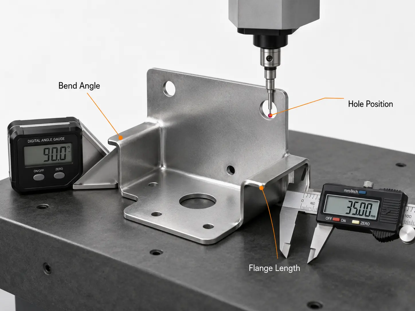
First-article inspection (FAI). Bend one part to completion before the production run. Measure every critical dimension — flange length, bend angle, hole position, squareness. If anything is off, adjust and re-run. First-article inspection confirms that the setup, tooling, and process can produce parts within specification before full production begins.
In-process checks. Production drifts — tooling wears, material varies, handling rhythms shift. A sample every 10–20 parts catches drift before scrap accumulates.
Measurement tools:
| What to Check | Tool | Typical Capability |
| Bend angle | Digital protractor, angle gauge | ±0.1° to ±0.3° |
| Flange length | Digital caliper | ±0.001 in (±0.02 mm) |
| Hole position (flat surface) | CMM, vision system | ±0.0005 in (±0.01 mm) |
| Squareness | 3-4-5 rule, granite square | Quick pass/fail |
| Surface finish | Visual, profilometer | Ra check if specified |
Features on a single flat surface can typically achieve tighter tolerances than features affected by multiple bends. As bends accumulate, tolerance stack-up increases. Understanding this gradient prevents specifying tolerances that cannot be consistently held on formed features.
Precision Sheet Metal Forming vs Sheet Metal Fabrication
Forming and fabrication are not the same thing, and conflating them creates confusion about where precision is gained or lost.
Sheet metal forming is a subset of fabrication — it covers shaping processes (bending, stamping, deep drawing, hydroforming, roll forming) where geometry changes through plastic deformation. Precision depends on material behavior, tooling geometry, machine control, and springback compensation.
Sheet metal fabrication is the full chain: cutting → forming → joining → finishing. Each stage adds its tolerance stack. Forming is often the hardest link because elastic-plastic behavior is less predictable than geometric cutting. When a part comes back out of tolerance, the root cause may not be forming — it could be weld distortion or a powder coat layer not accounted for in the dimension.
Applications of Precision Sheet Metal Forming
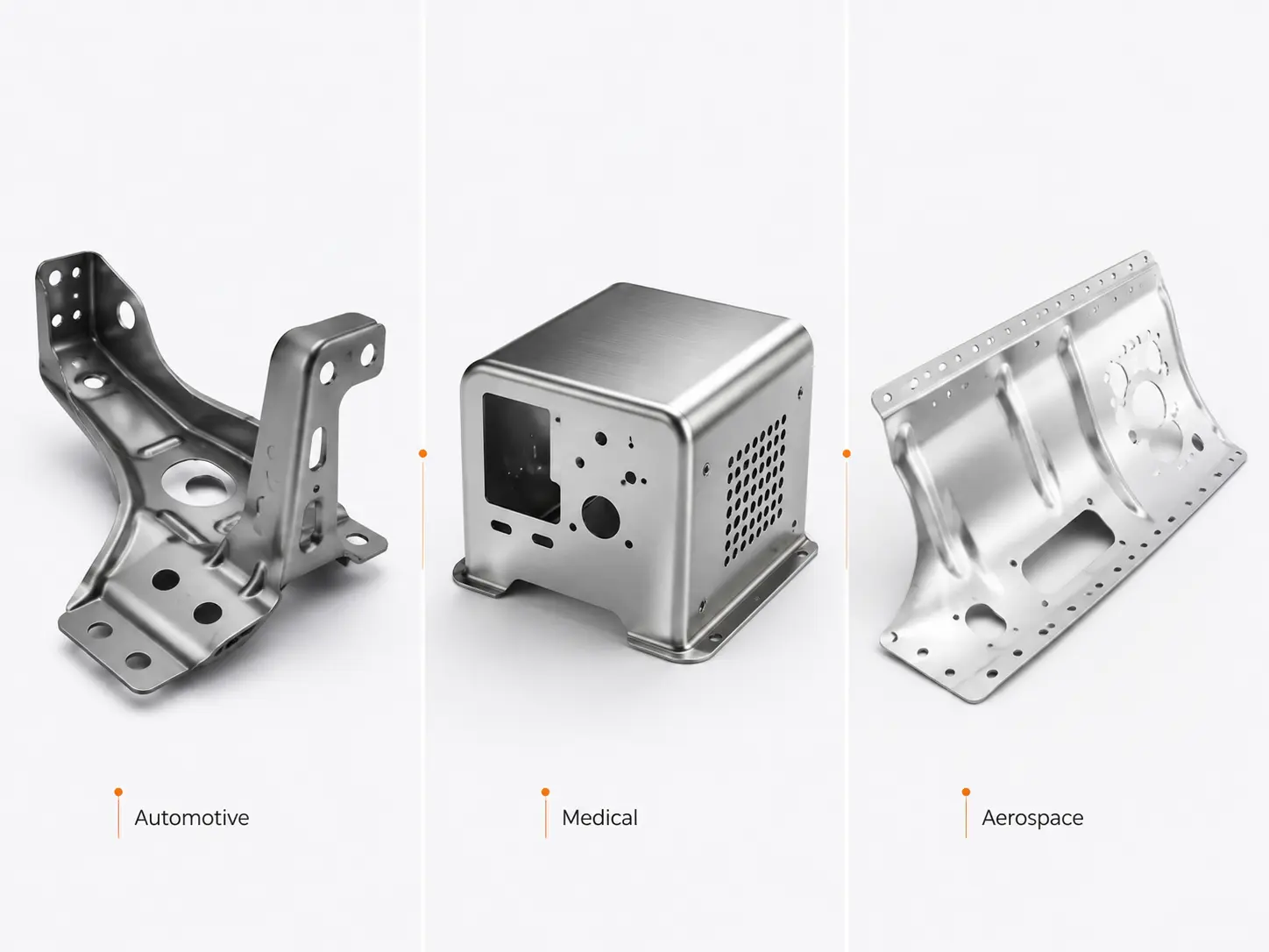
Automotive structural brackets. Body-in-white components require consistent bend angles across multiple flanges to maintain crash performance and assembly fit. Grain-direction control is critical because brackets are often formed in opposing directions from high-strength steel or aluminum sheet.
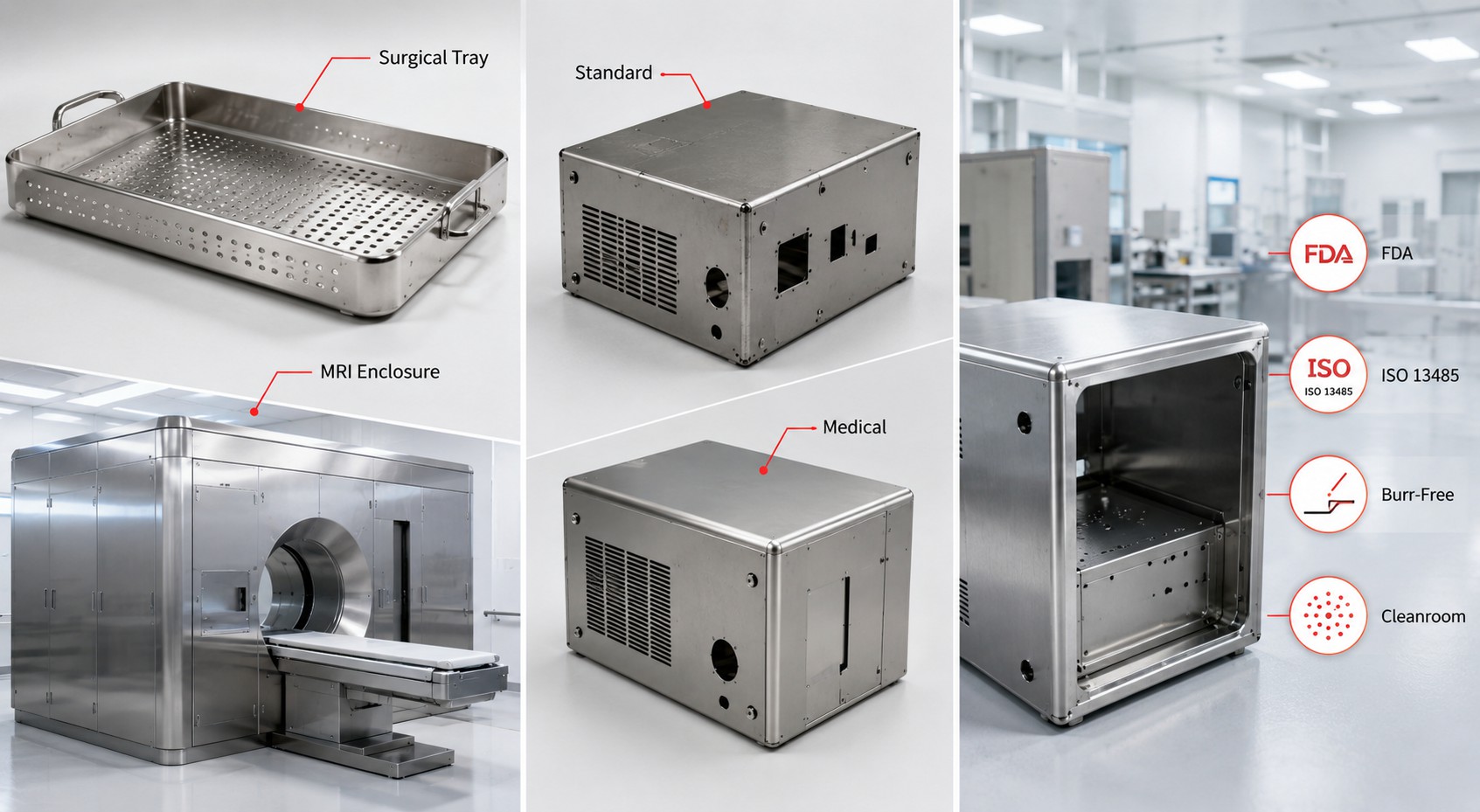
Medical device housings. Stainless steel 304 enclosures require consistent flange dimensions and bend angles to maintain proper assembly, gasket compression, and sealing performance.
Aerospace brackets and panels. Weight-critical parts in 2024/7075 aluminum or titanium require bend radii calculated to prevent stress-corrosion cracking. Grain orientation and surface finish are specified on the drawing and verified during FAI.
In each case, the seven practices determine whether the part fits, seals, or passes inspection.
Conclusion
Precision sheet metal forming depends on controlling seven variables as a system, not fixing them one at a time after the batch fails inspection.
Correct hole placement and bend relief prevent geometry issues at the design stage. Material selection — including grain direction — sets the physical limits. Tooling condition, bend sequence, springback compensation, and machine calibration keep the process stable. FAI and in-process checks catch drift before it becomes scrap.
If your next project involves tight-tolerance formed parts, upload the CAD file through RapidDirect platform for a free DFM report and instant sheet metal fabrication quote. The DFM check flags bend relief gaps, hole-to-bend conflicts, and grain-direction risks before production begins.
FAQ
Standard air bending with a CNC press brake holds ±0.3° on mild steel. Bottom bending can reduce that to ±0.1–0.2° for higher-tonnage setups. Aluminum 6061-T6 will always produce wider variation than mild steel because its springback is larger and less predictable.
Bend a test strip of the exact material, thickness, and grain orientation planned for production. Measure the resulting flange lengths and inside radius, then back-calculate the K-factor. If the flat pattern produces a part within 0.005 inches of the target, the K-factor is calibrated. Document the value in the job setup sheet.
The benchmark is 2.5 × material thickness plus the inside bend radius, measured from the hole edge to the start of the bend. If the hole sits inside that zone, expect distortion. The fix is to relocate it or move it to a secondary operation after bending. An automated DFM check can flag this before the file goes to production.
For one-off prototypes, builders often skip grain checks because cracking is obvious on inspection. For production, ignoring grain direction risks batch-level cracks, inconsistent springback, or angle drift that appears only after the first hundred parts. For any run exceeding a few dozen parts, specify grain direction on the drawing.
At minimum, ISO 9001:2015. For automotive: IATF 16949. For medical: ISO 13485. For aerospace: AS9100D plus ITAR registration. Beyond certifications, ask about in-house inspection capabilities — CMM, laser scanning, digital angle measurement — and material traceability for critical applications.