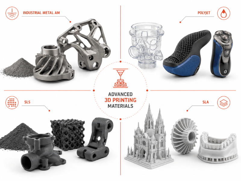

A 3D-printed part fresh off the bed rarely does its job. Layer lines, support scars, residual powder, and internal stresses all stand between a raw print and a part that fits, functions, and survives its intended use.
The gap is a design choice: every additive method leaves a different surface condition, and the right post-processing method closes that gap while the wrong one can scrap the part.
Choosing a method starts with three questions. What technology produced the part? What does the part need to do? And what can go wrong if the finishing step changes dimensions, weakens a feature, or varies across a batch?
What Your Print Technology Leaves Behind
Different print processes leave fundamentally different starting conditions, and that dictates which post-processing paths make sense.
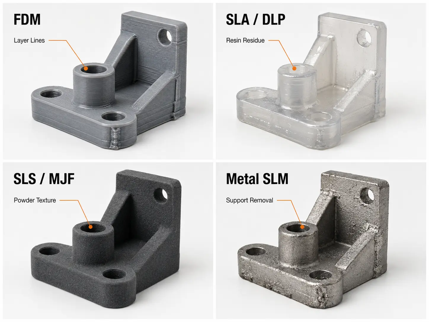
FDMparts typically show visible layer lines, with surface roughness depending on layer height and print parameters. Support structures leave contact marks on overhangs. Most FDM materials respond to sanding and some to chemical smoothing, but labor cost climbs fast on complex geometries.
SLAand DLP prints come off the platform smooth but carry uncured resin. Alcohol washing and UV post-curing significantly influence the final mechanical properties of resin prints. Clear SLA parts need additional polishing for optical clarity.
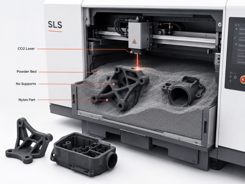
SLSand MJF parts arrive matte and slightly granular. Residual powder must be removed from internal channels and moving interfaces. These parts respond well to bead blasting, dyeing, and chemical smoothing.
Metal additive parts (SLM) add another layer of complexity. Support removal, stress relief, and machining on critical interfaces are part of the production route, not optional extras.
| Print Technology | Starting Surface | Core Post-Processing Needs |
| FDM | Visible layer lines, support scars, Ra 8–15 µm | Support removal, sanding or chemical smoothing |
| SLA / DLP | Smooth but uncured, resin residue | Alcohol wash, UV post-cure, optional polishing |
| SLS / MJF | Matte, granular, powder residue | Depowdering, bead blasting, dyeing or chemical smoothing |
| Metal (SLM) | Rough, residual stress | Support removal, stress relief, CNC machining |
The starting condition determines whether a finishing method can work at all. Applying acetone vapor to a PLA print does nothing. Sending an SLA part to annealing without post-cure wastes the cycle. The matching method to process is the first filter.
Surface Level Methods That Stay on the Outside
These methods improve appearance and feel without altering bulk substance properties.
| Method | Compatible Materials | Ra Improvement | Speed | Key Limitation |
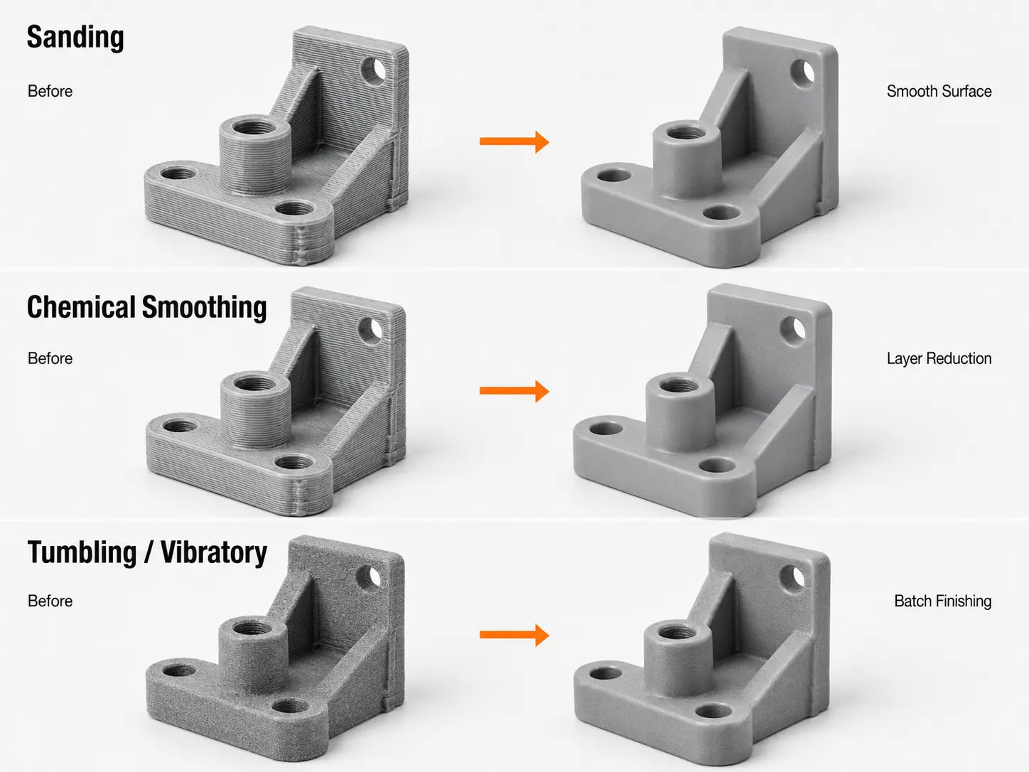
| Sanding | FDM, SLA, some SLS | Ra 8–15 µm → 1–3 µm (2000 grit) | Hours per part | Cannot reach deep recesses; operator-dependent |
| Chemical Smoothing | ABS, ASA, PA12, PA11 | Ra 8–15 µm → 0.8–2 µm | Minutes per cycle | Narrow material compatibility; slight dimensional change (±0.1 mm) |
| Tumbling / Vibratory | Metals, durable polymers | SLS Ra 10–15 µm → 3–6 µm | Hours per batch | Misses internal channels; can soften fine edges |
Sanding
Standard grit progression:
- 120–220 grit: removes visible layer lines and high spots
- 320–400 grit: smooths the surface, removes coarse scratches
- 600–800 grit: final prep before primer or coating
- 1000–2000+ grit: polishing stage for near-gloss results
Wet sanding is recommended above 600 grit for PLA and PETG to reduce heat buildup and improve surface consistency. Dry friction at fine grits generates enough heat to deform low-temperature thermoplastics. Sanding works on flat and gently curved surfaces but cannot reach deep recesses or undercuts. Hand sanding is labor-dependent.
Chemical Smoothing
Melts the outer layer with solvent vapor, then cools to a uniform finish close to injection molding. Material compatibility is the hard filter:
- Compatible: ABS, ASA (acetone vapor); PA12, PA11 (dedicated solvent systems)
- Not commonly compatible: PLA, PETG, PPSF, ULTEM
Ra drops from 8–15 µm as-printed to 0.8–2 µm. The surface also seals against liquids and gases.
Tumbling and Vibratory Finishing
Batch methods: parts in a drum with abrasive media, the motion does the work. Vibratory (oscillation) is faster; tumbling (rotation) is gentler. Media choice drives the outcome:
- Ceramic: aggressive cutting, deburrs metal prints
- Plastic: gentle deburring for softer materials
- Steel: burnishes to a bright finish
- Organic (walnut shell, corn cob): final polishing and cleaning
Neither method reaches internal channels.
Methods That Add Strength, Protection, and Function
These methods change mechanical properties, chemical resistance, and wear behavior rather than just appearance.
| Method | Primary Benefit | Best Material Fit | Typical Cost Driver | Watch For |
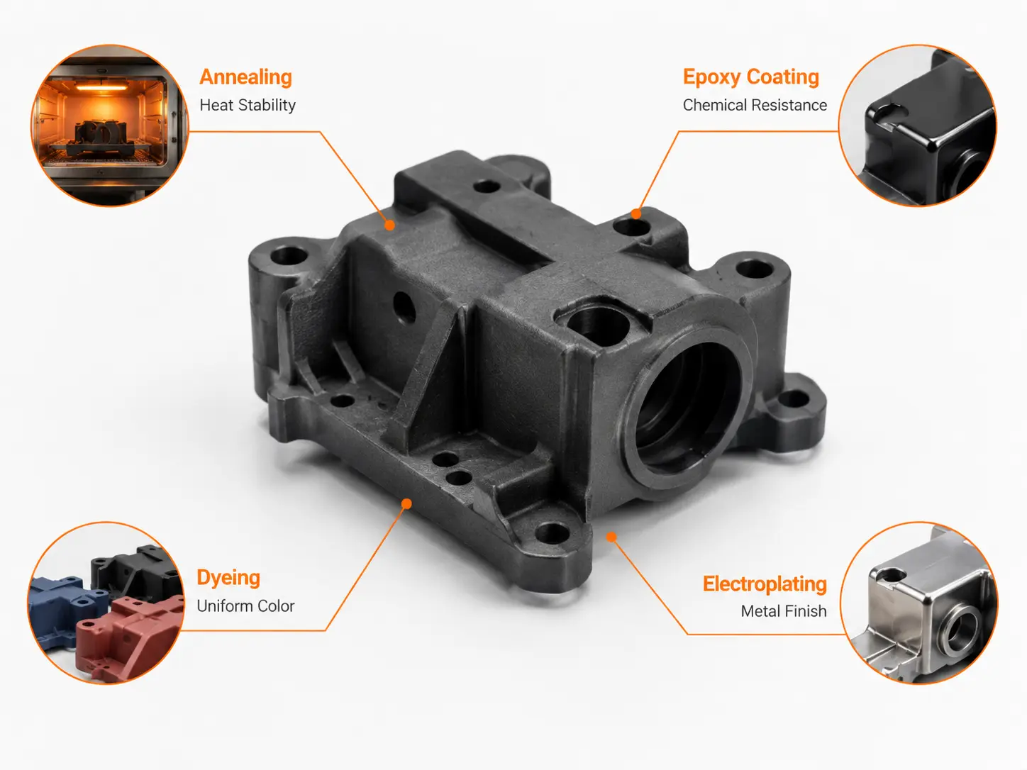
| Annealing / Stress Relief | Strength, thermal stability | Metal (SLM/DMLS), PLA, PEEK, Ultem | Furnace cycle time | Shrinkage and warping; must be designed for |
| Epoxy Coating / Infiltration | Surface sealing, chemical resistance | PLA, PETG, ABS, resin prints | Vacuum equipment + 3-hour cycle | Coating adds thickness; check mating features |
| Dyeing | Uniform color, no layer buildup | SLS/MJF nylon (PA12, PA11) | Bath temperature control | Nylon only; dark colors most consistent |
| Electroplating | Conductivity, wear resistance, mirror finish | ABS, resin prints | Multiple chemical stages; masking labor | Substrate must be made conductive first |
Annealing and Stress Relief
Not cosmetic. For metal SLM, residual stresses from the build can cause distortion in machining or service. Stress relief reduces those stresses through a controlled thermal cycle.
For polymers, the gains are substance-specific:
- PLA: improve heat resistance, with some formulations achieving HDT increases from around 60°C to above 100°C
- PEEK: crystallinity control improves thermal and mechanical performance
- Ultem: thermal treatment helps relieve internal stresses and stabilize properties
The universal warning: heat changes dimensions. Shrinkage and warping must be planned into the print geometry.
Epoxy Coating and Infiltration
Seals the surface at two levels:
- Hand-applied coating: practical for small runs and visible surfaces. Adds thickness that affects mating features.
- Vacuum infiltration: draws resin into pores throughout the surface layer. Airtight, chemically resistant. Cycle time is around three hours.
Dyeing
The go-to for SLS/MJF nylon parts:
- Immersion in a heated dye bath penetrates roughly 0.5 mm
- Adds no layer thickness, unlike paint
- Does not chip, peel, or wear off through handling
Electroplating
Deposits a real metal layer onto a polymer print:
- Copper: conductivity for EMI shielding
- Nickel: corrosion resistance and surface hardness
- Chrome: mirror finish, Ra as low as 0.2–0.8 µm possibly
The substrate must be made conductive first; ABS and resin prints are the most common candidates. Masking threads and mating surfaces adds labor.
Mechanical Improvement Beyond the Print
Surface-level and functional methods treat the part as printed. Mechanical improvement machines critical surfaces or adds hardware to achieve accuracy the printer alone cannot deliver.
| Method | Problem It Solves | Tolerance Improvement | Best For | Limitation |
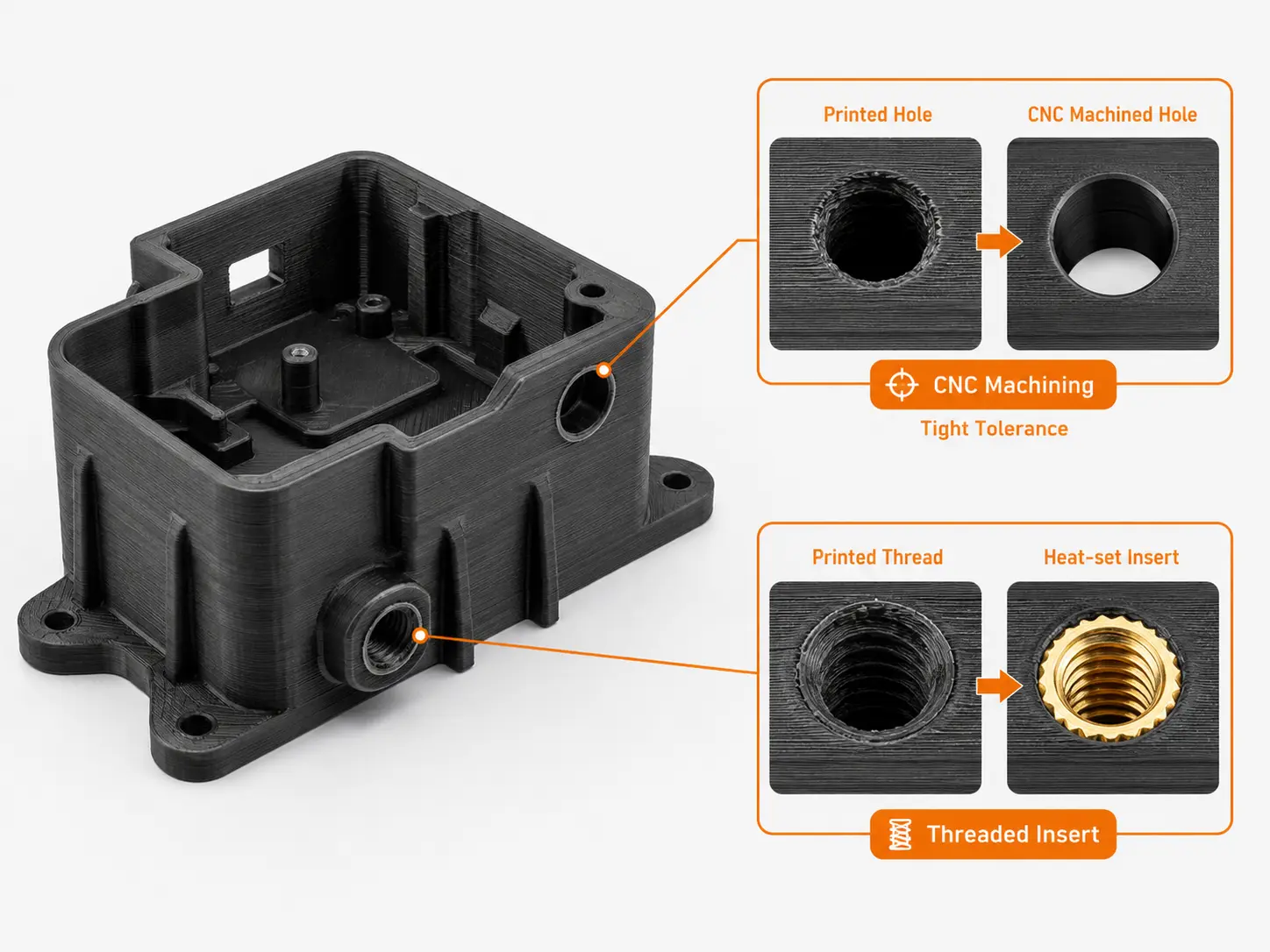
| CNC Machining (hybrid) | As-printed surfaces out of spec | Printed tolerance → machined (ISO 2768-m or tighter) | Datums, sealing faces, bores, threads | Adds secondary operation; requires fixturing |
| Threaded Inserts (heat-set) | Printed threads degrade under repeated assembly | Pull-out strength up to 10× printed threads | Housings, fixtures, serviceable assemblies | Hole must be slightly undersized; M2–M8 range |
CNC machining on printed parts follows a simple logic: print the form, machine the function. Datums, sealing faces, bores, and threads perform better when cut rather than printed to final tolerance. The advantage is dimensional reliability – a machined feature holds tighter tolerance and installs correctly every time.
At SHBD Metal, both capabilities sit under one roof. No supplier handoff between the print floor and the machine shop keeps lead times predictable and dimensional accountability in one place.
Threaded inserts solve a specific weakness: printed threads in polymer parts degrade under repeated assembly. A knurled brass sleeve is heat-set into a slightly undersized hole; the surrounding plastic locks it in place as it cools (M2–M8 standard). Pull-out strength is up to ten times a printed thread. For load-bearing connections that see repeated use, inserts are the baseline.
For higher-volume production requiring permanent integration of metal components into plastic parts, insert molding provides an alternative approach by embedding inserts directly during the molding method.
Choosing Methods for Your Application
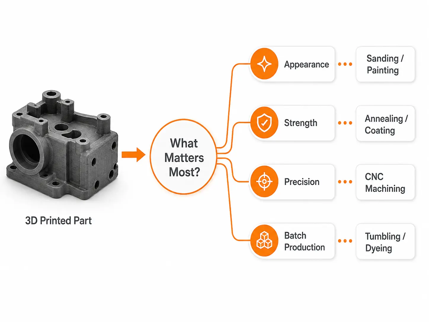
Post-processing is not a catalog to pick from. It is a chain of decisions starting with the part’s job. The same FDM print might need only support removal for an internal bracket but require sanding, primer, and paint for a customer-facing enclosure.
Four questions narrow the field:
- What is the part’s end use? A visual prototype prioritizes appearance. A functional test part prioritizes dimensional accuracy. An end-use part must balance both against durability and cost.
- What substance is it? Material compatibility is a hard filter. ABS accepts acetone vapor; PLA does not. Nylon takes dye; most resins do not. Metal parts need stress relief; polymer parts may not benefit.
- What tolerances must hold? Any method that removes or melts material can change dimensions. Sanding can round edges and thin walls. Vapor smoothing can close small holes. Annealing can cause warping. If a feature is tolerance-critical, the finishing method must be validated before it goes into production.
- How many parts? Hand sanding one prototype is manageable. Hand sanding 200 parts is a different calculation. Batch methods like tumbling and vibratory finishing trade some dimensional accuracy for throughput.
| Application | Primary Concern | Typical Path |
| Visual prototype / display model | Appearance, surface quality | Sanding + filler primer + paint; or vapor smoothing |
| Functional test part / jig | Dimensional accuracy, durability | Support removal + light sanding; threaded inserts if needed |
| End-use polymer part | Balanced finish, strength, cost | Bead blasting or tumbling + dyeing or chemical smoothing |
| End-use metal part | Precision, structural integrity | Stress relief + CNC machining on critical interfaces |
| Consumer-facing enclosure | Cosmetic quality, wear resistance | Chemical smoothing or epoxy + paint or electroplating |
Hand sanding is low-cost in materials but high in labor. Tumbling distributes labor across batches. Vapor smoothing adds roughly 20–40% to the part price but delivers injection-molding-grade surfaces. The right choice meets function, standard, and cost targets with repeatable output.
Build the post-processing plan at the quoting stage. A missing finishing step discovered after delivery means rework, delays, or a second production run.
Conclusion
Choosing 3D printing post-processing comes down to three anchors: the print technology, the substance, and part requirements. Start there, work backward to the method.
The most reliable post-processing plans are built before the first part hits the build plate. When post-processing costs approach injection molding tooling costs at higher volumes, switching processes may be the better path.
If the part requires CNC-machined interfaces or threaded inserts, keeping print and machining under one supplier simplifies lead time and accountability. Upload the CAD file for a free DFM review that includes post-processing recommendations, or get an instant quote for 3D printing with your required finishing.
FAQ
Sometimes. A bracket or internal fixture may work as-printed. But if the prototype needs to validate fit, assembly clearance, or sealing, the surface condition matters. Skipping post-processing on a tolerance-critical part can mask problems that surface later.
Support removal plus vapor smoothing on ABS and ASA. The vapor cycle takes minutes versus hours of progressive sanding. PLA has no chemical shortcut; sanding or coating is the path.
When a feature needs tight tolerance or reliable mating. Datums, bores, sealing faces, and threads all benefit from being cut rather than printed. Hand finishing smooths the surface but cannot correct geometry.
Yes. Thermal expansion and contraction shift dimensions during stress relief and heat treatment. The effect is predictable if the thermal cycle is part of the manufacturing plan. Print geometry should account for expected movement.
At minimum: the Ra specification the finished part will meet, a description of the finishing method and process control parameters, and dimensional inspection data on tolerance-critical features. For production runs, request batch-to-batch consistency data.