
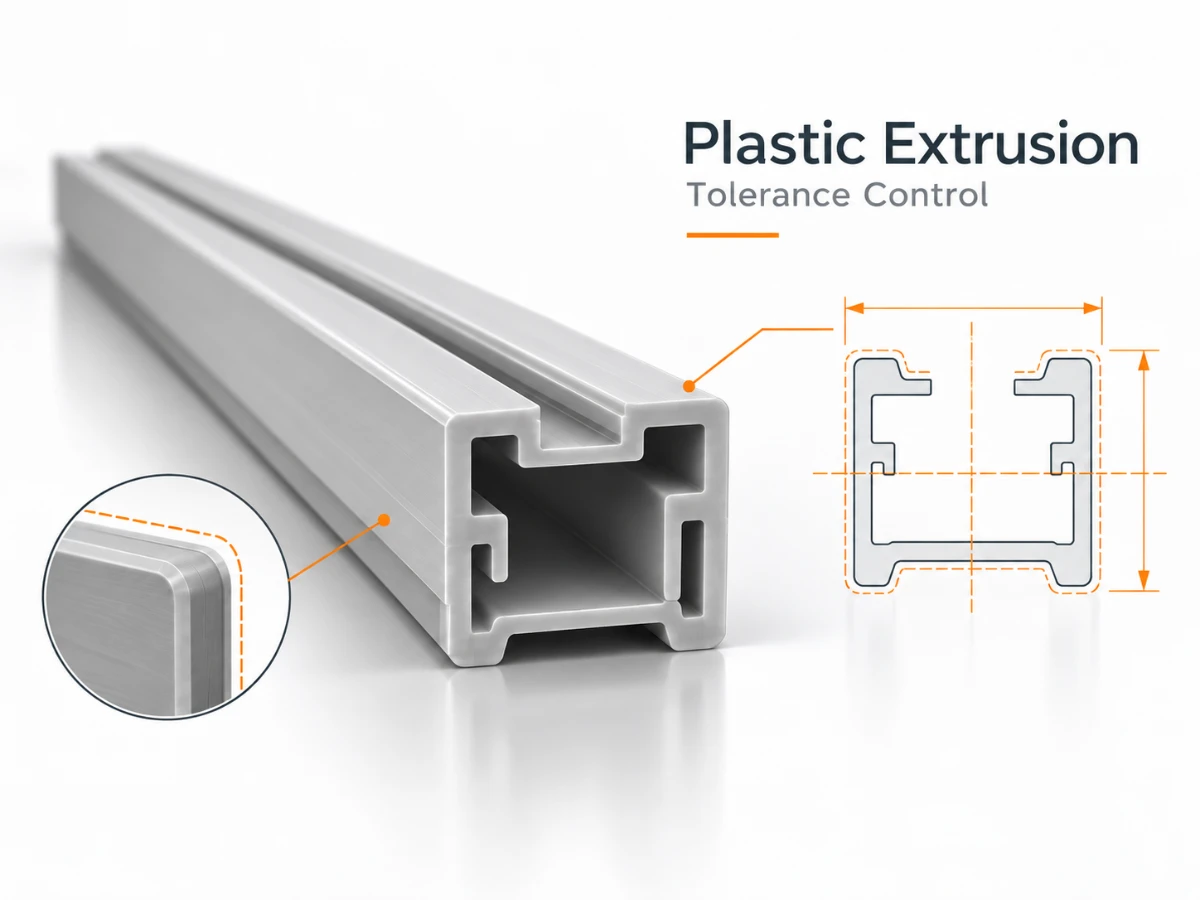
A profile that fails on the first sample is rarely a machine fault. The print asked for a wall ratio, an enclosed void, or a tolerance band the line cannot repeat, and the die was cut anyway. Tooling is section-specific, so the only road back is a second die.
This guide walks through the four mechanisms that cap what an extrusion can hold, the six tolerance classes a print should keep apart, the geometry checks that belong before tooling, and the gates a project clears on the way to release. Polymer-specific rules live in the PVC extrusion guide, and the line itself — screws, sequence, downstream equipment — is covered in our article on the plastic extrusion process.
Four Mechanisms That Cap What a Profile Can Hold
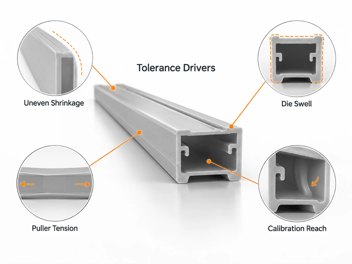
Four effects pull a finished profile away from its drawing, and each one lands on a different tolerance family.
Uneven shrinkage. Where two halves of a section cool at different rates, the profile pulls out of line. This is the largest single driver, and it reaches straightness, twist and cross-section at the same time. The compound decides how much it shrinks, and so does the amount of mass placed either side of the centreline.
Die swell. The extrudate leaves the die larger than the aperture, and how much depends on melt viscosity, line speed and wall thickness. Cross-section and wall thickness carry the result.
Puller tension. Tension from the puller stretches the profile along its length and thins whichever part of the section is weakest. Here, cut length and wall thickness both shift.
Calibration reach. Calibration pins the outside of the profile to nominal. Wherever the sleeve has no access — the inside of a void, or a face masked behind thick material — the wall is what moves.
Taken together, the four define the best any supplier can commit to ahead of cutting a die. Tightening a callout asks the process to beat whichever mechanism moves it, and the bill arrives as slower line speed, longer inspection, or scrap.
Six Tolerance Classes for an Extrusion Drawing
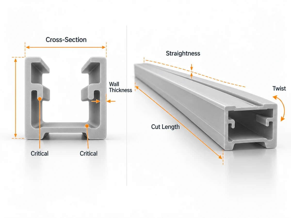
Extrusion tolerances are not one specification but six, and every class is driven, called out and inspected differently. Keeping them apart lets a print demand control where it matters and leave the rest alone. The profiles themselves differ from part to part; the classes do not.
Cross-Section Outline Dimensions
Tolerances on the cross-section cover the outline: overall width, overall height, and where features sit inside it. The die, the sleeve and the cooling rate drive them, and they respond to line speed. An open section is free to spring back once the puller releases it, so a dimension across it is harder to hold than the same dimension on a closed section.
Wall Thickness
Wall thickness is normally looser than the outline on the same print, because it depends on the balance between thick and thin regions rather than on the sleeve alone. Hold it only where it does a job: the lip that seals, a groove that mates, or the wall under a snap. Elsewhere the general band is enough, and inspection time stays on the features that matter.
Straightness and Camber
Camber and straightness measure how far a profile wanders from a straight line down its length. The callout is a maximum deviation across a length you state, and the span carries as much weight as the figure itself. One profile can clear the check over a short span and fail it over a longer one, so the span must appear in the drawing.
Twist
Twist means the section rotates around the length axis, and on asymmetric profiles it is the complaint that comes up most. Less error can be absorbed than with straightness, since it alters the way the profile seats against its mating part. Where a section cannot be balanced, twist commonly becomes the gate that decides assembly.
Cut Length
Length comes from the cutter rather than the die, and it is the dimension that stays stable for the whole run. The method sets the band: a saw on a stopped length holds tighter than a flying knife travelling with the line. For profiles that end up assembled into frames, end squareness and length count for more than the section itself.
Critical Versus Reference Dimensions
Control is not owed to every dimension. A handful of dimensions — two or three that carry function or mate with another part — earn inspection; the remainder can be reference dimensions at general tolerance. Banding everything raises inspection cost, scraps parts over dimensions that carry no function, and hides the requirement that actually matters. Molding drawings follow the same logic, which is why the injection molding design guide and injection molding tolerances separate classes instead of blanketing a sheet.
| Dimension family | What moves it | How to call it out | How to inspect it |
|---|---|---|---|
| Cross-section | Shrinkage, calibration | Nominal plus a band, feature by feature | Calipers on a cut section |
| Wall thickness | Die swell, wall balance | A band kept separate from the outline | Fixed measuring points on a cut section |
| Straightness | Cooling, weight of the section | Maximum deviation over a stated length | Surface plate or straightedge |
| Twist | Uneven cooling on asymmetric sections | Maximum angular deviation over a given length | Reference face against a gauge |
| Cut length | Cutting method, line speed | A band the chosen cut method can hold | Tape or a fixture gauge |
| Critical dimensions | Marked by the designer, not a physical trait | Flagged critical, remainder at general tolerance | Full inspection on critical dimensions only |
Geometry Rules That Decide the Available Tolerance Window
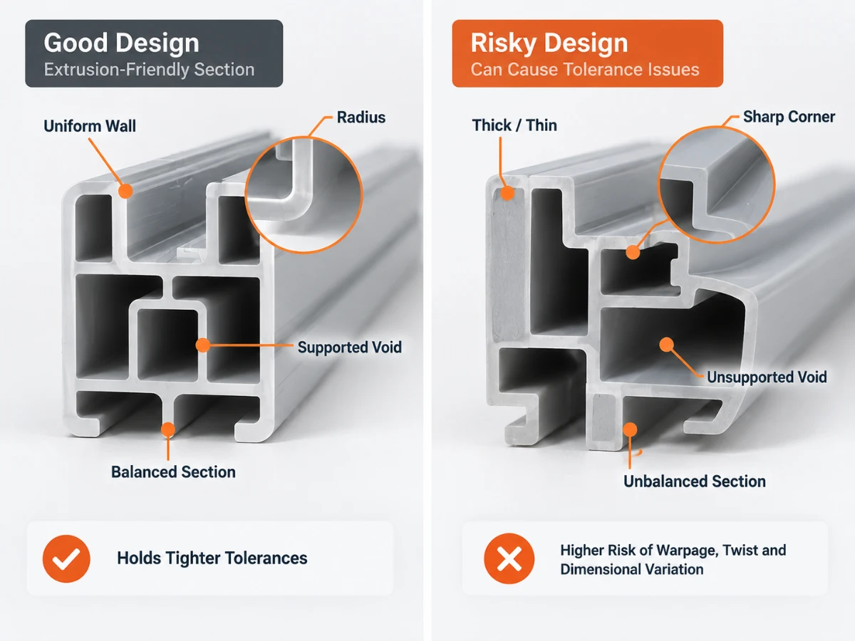
Five geometry decisions determine how much of the tolerance window is left before process control has to compensate. Ignore any one of them and the tolerance class it puts at risk will not hold, no matter how the die is cut. What follows is what breaking each rule costs; the material-specific version of the rules sits in the PVC extrusion guide.
| Geometry rule | Class put at risk | Failure mode |
|---|---|---|
| One nominal wall | Wall thickness, straightness | Thick regions pack out while thin walls starve, after which the section pulls to one side |
| Stepped thick-to-thin transitions | Wall thickness | The thin end fills late and arrives undersize |
| Radiused internal corners | Cross-section, surface | Melt slows in the corner, so it fills late or leaves a line |
| Voids supported through calibration | Cross-section, wall thickness | The wall dimples, or the section collapses under vacuum |
| Symmetry about the centreline | Straightness, twist | Uneven cooling bows the profile and rotates the section |
Two of those rows are worth settling on paper rather than at the bench. Both symmetry and void support consume budget that is available at the design stage; a section ignoring them begins with less room than the drawing pretends.
What Section Imbalance Costs in Dimensions
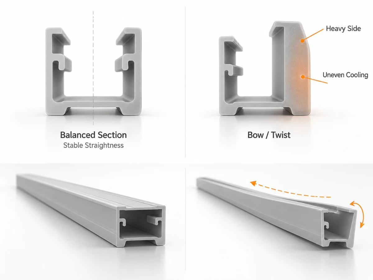
Mass distribution decides a profile design before the outline does. A section with a heavy leg on one side bows toward the thin side on every run, and the mechanism is worth stating plainly. Heat lingers in thick regions, so they shrink later and by a larger amount than the thin walls alongside. Since even shrinkage is impossible, the section settles the mismatch by bending — and faster line speeds make it worse.
Rarely does the problem appear as a wall outside its band. Instead it shows up as bow, camber or twist building along the length.
The cheapest fix on the table is symmetry about the centreline, and it costs no more than a revision to the drawing. When function forbids symmetry — a single-edge lip, a flange on one side — widen the straightness and twist limits and inspect to them instead of fighting the imbalance in the die. Die correction can redistribute flow. A mass difference built into the section lies beyond its reach.
How the Polymer Shifts the Tolerance Budget
The polymer changes the geometry decision through three properties, and only the first usually gets discussed.
How far the finished profile draws away from the die is a function of shrinkage. PE and PP, being semi-crystalline, shrink further than amorphous polymers such as PVC, ABS and PC, so a section in balance within one family may sit out of balance in another. Stiffness decides whether a thin wall needs a rib and how much puller tension the profile takes. Outdoor service decides whether the extruded surface is good enough on its own, or whether a cap layer has to shield a cheaper core.
The practical question is not which polymer is better. The real question is whether the section stays balanced once the polymer is swapped, and whether the drawing's tolerance classes can still be met in the new material. Shrinkage data by grade sits in the materials library.
Design-Related Defects on a Running Profile
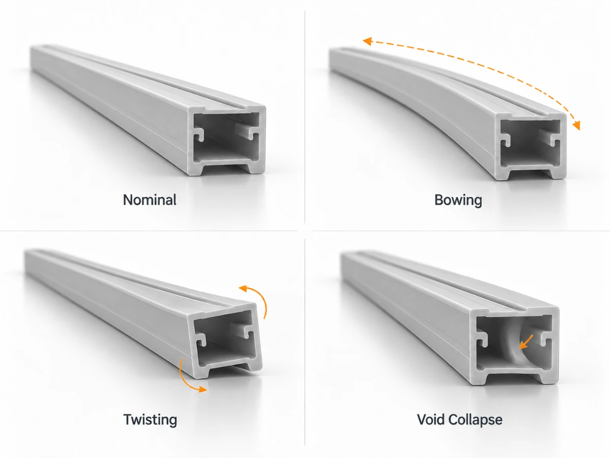
Most defects on a running profile trace back to a geometry decision rather than to the machine. The final column is the commercially decisive one: it splits defects a die correction can still reach from those that send the section back to the drawing board.
| Symptom | Root cause in the design | What to change | Die work or redesign |
|---|---|---|---|
| Bowing | Mass on one side, uneven cooling | Balance the section, or cool where the mass sits | Mostly design |
| Twisting | A section that cools asymmetrically at two rates | Restore symmetry, or widen and inspect the twist callout | Design |
| Surface lines | Flow restriction at a corner, thin section filling late | Open the radius, or even out the wall | Tooling if flow, design if geometry |
| Uneven wall thickness | Thick and thin areas filling at different rates | Step the transition over a distance | Tooling if flow, design if geometry |
| Hollow section collapse | Void unsupported at the calibration point | Add support, pressurize the void, or divide it | Design |
| Poorly formed corners | Internal radius too sharp to keep melt moving | Increase the internal radius | Design |
Design Review Before the Die Is Cut
The review is the last point where a design-for-manufacturing question costs a drawing revision instead of a die. It comes down to two lists — checks on the section itself, and what the drawing has to provide.
Design-for-Manufacturing Checklist
- Is the cross-section continuous end to end?
- Do all walls share a single nominal thickness?
- Do thick-to-thin transitions step gradually instead of abruptly?
- Does every internal corner carry a radius?
- Is each hollow section supported at the calibration point?
- Have the two or three critical dimensions been flagged?
- Are straightness, twist and cut length called out as separate classes?
- Is the section in balance about its centreline?
- Have the cosmetic surfaces been identified?
- Are the secondary operations and the annual volume both known?
What the Print Has to Carry
A drawing carrying the following gets quoted faster and sampled closer to nominal:
- Nominal cross-section with dimensions and tolerances
- Polymer and grade
- Critical dimensions and inspection datums marked, with the remainder at general tolerance
- General and special tolerance bands kept apart
- Straightness and twist limits, quoted over a stated length
- Cut length and end squareness
- Colour, surface and cosmetic-face requirements
- Secondary machining requirements and sample quantity
Where secondary machining holds tighter features, call the machining tolerances out separately from the extrusion bands.
From DFM Sign-Off to a Released Profile
Approval is not one event. Between an approved section and a released part sit three gates, and every one of them can return the project to the drawing.
Die Build and Flow Balancing
The die is cut from the approved section, and the first run is a trial rather than a production run. Bench work sets the flow balance across thick and thin regions, and the calibrator is matched to the section only after the first extrudate has been measured.
The First-Article Report
Evidence that the profile meets its drawing comes from the first-article sample. Expected in that report: cross-section measurements at named points, wall thickness at the same points, straightness and twist over the declared length, and cut length. An outline-only sample says nothing about whether the walls came in, and the walls are where the risk concentrates.
What Die Correction Can and Cannot Fix
Die correction fixes flow balance, wall thickness distribution and dimensional drift. A section unbalanced by design, a wall too thin to fill, and shrinkage the die was never cut for all sit outside its scope — each returns to the geometry. Where that boundary falls settles both who pays for the correction and the fate of the schedule.
Getting the Section Reviewed
Custom profile work starts with the print review, not the die. SHBD Metal runs that review against the geometry rules above, agrees the wall balance and the tolerance classes that need holding, and confirms polymer and grade against the drawing. Tooling is released only once the review is closed.
Features That Belong in Secondary Machining
Features that vary along the length — local snaps, cross-holes, pockets and mating faces — are better cut after extrusion than forced into the die. CNC machining and finishing handle them without changing the section.
How a Project Starts
Send the section with the drawing for a quote. The review covers wall balance, void support, radii and tolerance strategy before any die is committed, so a fix costs a drawing revision instead of a tool.
Conclusion
These are the guidelines that decide whether a profile can be made at all. A section in balance, with a single nominal wall and supported voids, meets its drawing at general tolerance. One with a heavy leg and an unsupported cavity resists every callout printed on the sheet.
Scrap is not the only thing this mistake costs. Tooling is section-specific, so an imbalance that only surfaces at the first sample returns the project to design with the die already paid for. Hence the case for a design-for-manufacturing review ahead of tooling — the same reasoning that underlies every other design guide on this site.
If the section is drawn, send it with the print for a quote. Nothing is cut until wall balance, void support, internal radii and tolerance strategy have all been reviewed.
FAQs
Can a profile be extruded exactly as drawn?
Often it can, and three things decide it — wall balance, void support, and whether the tolerance callouts match what the line repeats. SHBD Metal checks all three at DFM review before tooling is released, and a section that fails comes back quoted with the correction rather than refused.
What has to be on the print before a profile tolerance can be verified?
Three: a datum behind each callout, a reference length attached to every straightness or twist limit, and a way to measure dimensions calipers cannot reach. Omit any one and the same part can pass under one inspector and fail under another. SHBD Metal completes them at DFM review and returns the drawing ready to quote.
Do tight tolerances survive on a complex hollow section?
They do, provided the tight callouts land on faces the line controls. The limit comes from calibration reach: a void the vacuum sleeve cannot support, or a face shielded by thickness, will move. That is why hollow sections are reviewed for internal support before a print is approved.
Suppose the first-article sample misses the drawing — what then?
Treat the first sample as a trial, not a verdict. One correction round is normal, while bench work settles flow balance and wall distribution. Beyond that, a miss usually points to geometry — a section out of balance, or a wall too thin to fill — and it returns to the drawing rather than to the die.
Is it possible to extrude a snap-fit feature into a profile?
It is, as long as the undercut is shallow enough for a fixed die and the flexing part is thin-walled. Such a feature runs the full length, so it behaves as a continuous rail rather than a local clip. Local snaps, pockets and cross-holes are better cut after extrusion.