
Sheet metal design follows rules that other manufacturing processes do not. A feature that machines perfectly on a CNC mill — a deep pocket, a sharp internal corner, a thin wall — can be impossible, expensive, or structurally weak in sheet metal. The difference comes down to one word: bending. Every flange, bracket, and enclosure starts as a flat blank, and every bend pulls material, stretches it, and changes where holes end up.
At SHBD Metal, our CNC machining and sheet metal fabrication teams share one engineering review process, so design errors are caught before tooling is cut. This guide explains the core rules of sheet metal design — bend allowance, bend radius, feature placement, and the mistakes that inflate cost and lead time.
Why Sheet Metal Design Rules Matter
Sheet metal parts are produced by cutting a flat pattern, then forming it. The flat pattern is not the same shape as the finished part — the material stretches and compresses around each bend, so the blank must be calculated, not guessed. If the blank is wrong, holes drift from their positions, flanges come up short, and parts that fit perfectly in CAD arrive at assembly with visible gaps.
Design rules exist for three reasons: to keep parts manufacturable with standard tooling, to keep cost predictable, and to keep the formed part within tolerance. Parts that respect the rules run through laser cutting, punching, and bending without special setups. Parts that ignore them trigger rework loops, custom tooling, and scrap.
Bend Allowance and K-Factor
When a sheet is bent, the material on the inside of the bend compresses while the material on the outside stretches. Somewhere between the two surfaces lies the neutral axis — a plane that keeps its original length. The distance from the inner surface to the neutral axis, expressed as a fraction of material thickness, is the K-factor. For most aluminum and steel alloys it sits between 0.30 and 0.50, with 0.44 a common default for air bending.
Bend allowance is the arc length of the neutral axis across the bend. It is the extra material the flat pattern must include so that the finished flanges land at the right dimensions:
Bend Allowance = Angle × (π/180) × (Inside Radius + K-factor × Thickness)
CAD packages calculate bend allowance automatically when the K-factor and radius are set correctly. Keep those settings consistent between your CAD file, your drawing, and your supplier's press brake — when they drift, every bent dimension drifts with them.
Bend Radius and Minimum Flange Length
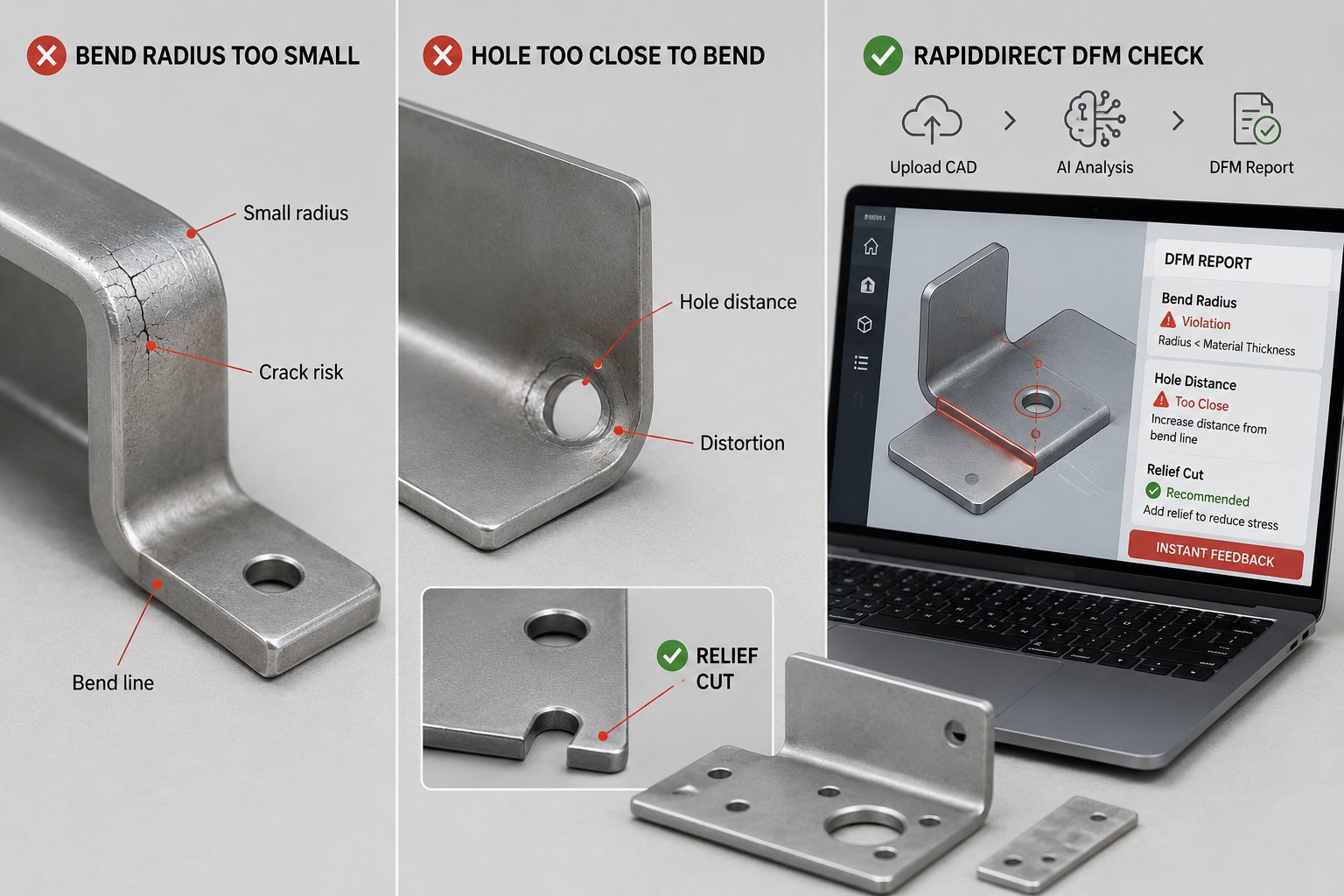
The inside bend radius should be at least one material thickness for most alloys (for example, 1.5 mm radius on 1.5 mm steel). Sharper radii are possible with special tooling, but they risk cracking, thinning, and tooling wear. As a rule of thumb:
- Minimum inside radius ≈ 1× material thickness for ductile alloys (mild steel, aluminum 5052, brass).
- Larger radius (1.5–3× thickness) for harder alloys like 6061-T6 aluminum or spring-tempered stainless.
- Minimum flange length ≈ 4× thickness + bend radius — shorter flanges cannot be gripped by standard press brake dies.
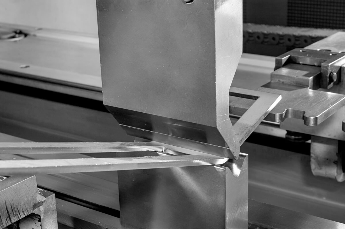
Another consideration is springback: after the punch releases, material springs back toward its original angle, more so in high-strength alloys and larger radii. The press brake compensates by over-bending slightly. Parts holding tight angular tolerances should use generous radii and ductile materials.
Hole, Slot, and Feature Placement
Bending distorts nearby features, so holes and slots need clearance from bend lines. Follow these minimum distances:
- Holes near bends: keep the hole edge at least 2× material thickness + bend radius away from the bend line, or the hole will deform into an oval.
- Minimum hole diameter: at least 1× material thickness — smaller holes risk punch breakage and burrs.
- Slot width: at least 1.5× thickness; long narrow slots are prone to warping during forming.
- Distance to edge: keep holes at least 2× thickness from a sheared edge to prevent the edge from bulging.
- Threads: specify hardware (rivet nuts, weld nuts) instead of tapped holes thinner than 1.2 mm — threads in thin sheet strip out easily.
Text, logos, and part numbers are best added as laser-etched or punched markings in flat areas — never across a bend line, where the mark will stretch and distort.
Corner Reliefs, Notches, and Tabs
Adjacent bends meet at corners, and without relief the material tears or bunches. A corner relief — a small circle or notch cut at the intersection — lets each flange form independently. Standard practice is a relief radius of at least half the material thickness, or a rectangular notch sized to the bend.
Rules for notches and tabs:
- Notch width at least 1× thickness; notch depth at least 1× thickness.
- Avoid sharp inside corners in notches — add a 0.5–1 mm radius to prevent cracking and to make laser cutting clean.
- Tabs that fold 90° need the same bend radius and relief rules as any other flange.
- Countersinks and embosses need 3× thickness clearance from other features.
Tolerances and Material Selection
Sheet metal tolerances are looser than machined tolerances — bending introduces cumulative variation that milling does not. Typical forming tolerances are ±0.3–0.5 mm for bend positions and ±1° for angles, while laser-cut profiles hold ±0.1–0.2 mm. Locate critical holes on a single flat face, and use machined features where tolerances tighten. Our quality assurance process covers the inspection methods used to verify formed parts.
Material choice drives both bendability and cost. Common sheet metals include low-carbon steel (cheap, formable, must be protected from corrosion), galvanized steel, stainless steel 304/316, and aluminum 5052 and 6061. Alloy temper matters: 5052-H32 bends easily, while 6061-T6 is stronger but cracks at tight radii. Compare mechanical properties across the full range in our materials guide.
Common Sheet Metal Design Mistakes
These are the errors our engineering team sees most often in incoming CAD files:
- Designing to machined tolerances. Specifying ±0.05 mm across a formed part guarantees rework. Allow ±0.3 mm or more on formed dimensions and hold tight tolerance only where it matters.
- Ignoring bend direction. Forming against the material grain increases cracking risk. Bends parallel to the grain need larger radii, especially in aluminum.
- Holes too close to bends or edges. Deformation, ovality, and edge bulging are the predictable results.
- Sharp internal corners. Internal corners should carry a radius of at least 0.5–1× thickness; sharp corners concentrate stress and complicate tooling.
- Uniform wall thickness everywhere. Unlike machined parts, sheet metal parts cannot mix 1 mm and 4 mm walls — the entire blank is one gauge. Choose the gauge for the most demanding area.
- Forgetting assembly access. Fastener clearance, welding access, and tool access for bending should be verified in the flat and formed states.
- Over-tolerancing angles. ±0.5° bend angles are achievable; ±0.1° is not, without grinding and inspection effort that few projects justify.
Frequently Asked Questions
What is the minimum bend radius for sheet metal?
As a general rule, the inside bend radius should be at least one material thickness for ductile alloys like mild steel and 5052 aluminum. Harder alloys such as 6061-T6 aluminum and high-strength stainless need 1.5–3× thickness. When in doubt, larger radii are cheaper and safer.
How is bend allowance calculated?
Bend allowance is the arc length of the neutral axis across the bend: Angle × (π/180) × (Inside Radius + K-factor × Thickness). The K-factor, typically 0.30–0.50, locates the neutral axis relative to the inner surface. Your CAD software applies this automatically once the K-factor and radius are set correctly.
Why do holes deform when they are near a bend?
During bending, material inside the bend compresses and material outside stretches. A hole whose edge falls inside that zone is pulled into an oval. Keeping hole edges at least 2× thickness plus the bend radius away from the bend line avoids the problem.
What tolerances can sheet metal fabrication hold?
Laser-cut profiles typically hold ±0.1–0.2 mm, punch features ±0.1 mm, and formed (bent) dimensions ±0.3–0.5 mm with bend angles of ±1°. Tighter values are possible with careful process control, but they raise cost. Specifying tolerance only where functionally required is the most economical approach.
Can sheet metal parts be painted or coated?
Yes. Common finishes include powder coating, painting, anodizing (aluminum), zinc plating, and passivation for stainless steel. Finishes add microns to the surface, so they should be selected before tolerances are locked. Machined features can be added after forming when tolerances demand it.
Get Your Sheet Metal Parts Quoted
Good sheet metal design is the cheapest insurance a project can buy. At SHBD Metal, our engineers review every file for bend feasibility, feature placement, and tolerance realism before quoting — and we flag issues before they become rework. From laser cutting and punching to press braking, welding, and finishing, the whole process runs under one roof.
Upload your CAD files today and receive a detailed quote within hours, complete with DFM feedback, finish options, and lead times. Let us turn your flat pattern into parts that fit the first time.