In modern manufacturing, CNC machines have replaced manual machines for most applications. Computer-controlled machinery can cut parts with a high level of precision, saving machinists time and ensuring accuracy.
But as CNC machines have replaced traditional machines, CAD files have taken the place of technical drawings as the primary source of machining instructions. Technical drawings are still useful for human machinists, but CAD files contain the digital information that will be transferred to the machine.
Our CNC machining centers can do a lot, but they can’t read your handwriting.
This article serves as a basic guide to CAD files for CNC machining, helping you prepare a suitable CAD file that can be uploaded to our online platform, ready for machining.
What is a CAD file?
A computer-aided design (CAD) file is a digital document containing information about a 2D or 3D model.
It mainly specifies geometric dimensions, but it may also contain material properties and manufacturing information.
CAD files are prepared using CAD software, a type of computer application used by engineers, designers, and other professionals to create 2D and 3D models. CAD software has many advantages over manual drafting, such as precision, transferability, and even simulation.
However, CAD files must be exported into the right format before they can be used by CNC machines and other manufacturing technologies.
A typical workflow goes like this:
- The engineer/designer(you) designs the part using CAD software and exports a neutral CAD file.
- The machinist(3ERP) imports the CAD file into computer-aided manufacturing (CAM) software to define the ideal cutting instructions for the part, then uses a CAM post-processor to export a G-code file that can be read by the specific CNC machine.
- The CNC machine(3ERP) reads the G-code file and cuts the physical part.
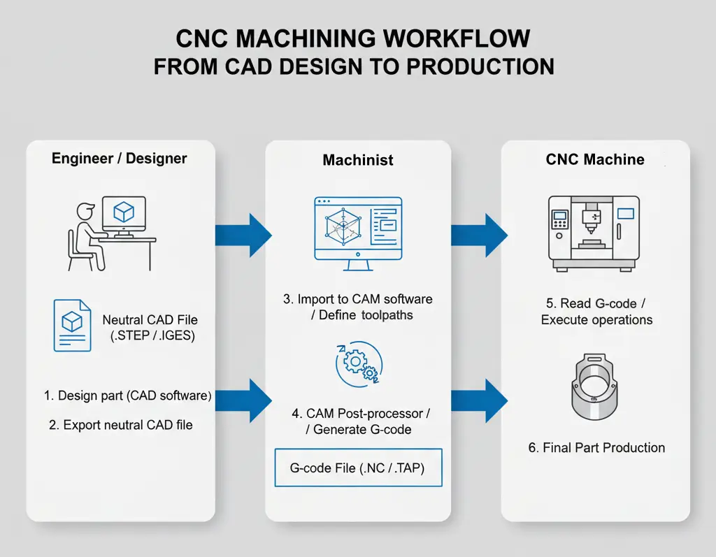
Common CAD File Types for CNC Machining
A few different CAD file formats exist, just like different image formats exist (JPEG, PNG, GIF, etc.). These formats were developed at different times for different purposes.
First, it is important to understand the difference between neutral and native CAD formats.
- Neutral or universal CAD formats like STEP and IGES are standardized formats that can be read by most CAD or CAM software. They contain the core geometric information about the model.
- Native CAD formats like PRT and SLDPRT contain more information than neutral file formats, including the model’s full “history tree,” which documents individual changes made by the designer. However, these files can only be opened in the software in which they were made.
A common mistake made by first-time customers is trying to upload native 3D CAD files that aren’t compatible with our CAM software and CNC machines.
Fortunately, most CAD software provides the option to export files in a neutral format, even if the default file format is native.
The table below compares some of the main CAD file formats for CNC machining.
| Format | Extension | Native | Geometry | Compatibility | 3ERP Upload |
| STEP | .stp, .step | No | Full solid | All CAM systems | ✅ |
| IGES | .igs, .iges | No | Surface | Most CAM systems | ✅ |
| X_T | .x_t, .x_b | No | Full solid | Most CAM systems | |
| SAT | .sat | No | Full solid | Most CAM systems | |
| DXF | .dxf | No | 2D vector | Most CAM systems | ✅ |
| DWG | .dwg | Yes | 2D vector | Autodesk AutoCAD | |
| PRT | .prt | Yes | Full solid + metadata | PTC Creo, Siemens NX | |
| SLDPRT | .sldprt | Yes | Full solid + metadata | Dassault Solidworks | |
| F3D | .f3d | Yes | Full solid + metadata | Autodesk Fusion |