Wall thickness is an important factor to achieve optimal results when using CNC machining for your projects. In this guide, we’ll discuss the significance of wall thickness in CNC machining and how it directly affects the quality and performance of the parts.
What is Wall Thickness in CNC Machining?
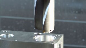
Wall thickness , an important CNC machining parameter, is the specific measurement of the material layer between two parallel surfaces of a part. In simpler terms, wall thickness is what holds your part together, providing it with the necessary strength to withstand external forces while remaining lightweight and efficient.
In the CNC machining process, wall thickness needs to be calculated in relation to the material properties and the part function. For example, thin walls might be needed for lightweight applications but require precise machining to avoid warping or breaking. Thicker walls can give more durability but will add weight and material cost, making the part less efficient or more expensive to produce.
Why is Wall Thickness Important in CNC Machining?
Wall thickness is important in CNC machining because it directly affects the structural integrity and mechanical stability of the parts being produced. Parts with inappropriate wall thickness—either too thin or too thick—can lead to a range of issues, from structural failures to excessive machining costs.
The structural integrity of a part is its ability to withstand applied forces without deforming or breaking.
Thin walls may be prone to deformation under load, leading to failure during operation. This is particularly important in industries where parts are subjected to high stress, such as automotive or aerospace sectors.
On the other hand, excessively thick walls, while providing more strength, can lead to unnecessary material usage, increasing both weight and cost without any added functional benefit.
Mechanical stability refers to the part’s ability to maintain its shape and dimensions during and after the machining process. Proper wall thickness ensures that the part remains stable throughout machining, reducing the likelihood of issues such as tool deflection or vibrations that can affect the final surface finish.
This stability ensures tight tolerances and achieving the desired surface finishes, especially in precision applications.
How Does Wall Thickness Impact Material Selection and Performance?

When selecting materials for CNC machining, wall thickness must be carefully considered to ensure that the material’s properties align with the design’s functional requirements.
For example, metals like aluminum and brass can be machined with relatively thin walls due to their strength and rigidity.
In contrast, plastics may require thicker walls to maintain structural integrity, especially under load or in high-temperature environments.
The machining process itself also affects material selection. Certain materials, such as stainless steel, require specific cutting tools and machining techniques to achieve the desired wall thickness without compromising the part’s performance.
Additionally, the surface finish of the machined part can be influenced by the wall thickness, with thinner walls often requiring more precise finishing processes to achieve a smooth and accurate result.
Wall thickness impacts the following aspects of material performance:
- Structural Strength: Thicker walls provide greater structural strength, which is crucial for parts that must withstand significant mechanical loads.
- Thermal Stability: The ability of a material to resist changes in shape due to temperature variations can be affected by wall thickness, especially in high-performance applications.
- Weight: Wall thickness directly impacts the weight of the final part, which is a critical factor in industries such as aerospace and automotive where minimizing weight is essential.
- Cost: Thicker walls generally mean more material is used, leading to higher costs. Therefore, optimizing wall thickness is key to balancing performance and cost-effectiveness.
What is the Range of Wall Thickness for Different Materials?
Different materials have different minimum and maximum wall thicknesses that can be achieved while maintaining structural integrity and machinability.
Here’s a list of common materials used in CNC machining, along with their typical wall thickness ranges:
Aluminum:
- Minimum Wall Thickness: 0.5 mm
- Maximum Wall Thickness: 10 mm
Stainless Steel:
- Minimum Wall Thickness: 1 mm
- Maximum Wall Thickness: 15 mm
Brass:
- Minimum Wall Thickness: 0.5 mm
- Maximum Wall Thickness: 12 mm
Plastics (e.g., ABS, Polycarbonate):
- Minimum Wall Thickness: 0.3 mm
- Maximum Wall Thickness: 8 mm
Titanium:
- Minimum Wall Thickness: 1 mm
- Maximum Wall Thickness: 20 mm
Carbon Fiber Composites:
- Minimum Wall Thickness: 0.5 mm
- Maximum Wall Thickness: 10 mm
How Wall Thickness in CNC Machining Influences Machinability and Tooling?

The thickness of the walls in a part dictates the approach to machining, influencing factors such as tool selection, machining speed, and precision. Understanding how wall thickness affects these aspects is essential for achieving high-quality parts with optimal performance.
- Impact on Machinability: Machinability refers to how easily a material can be machined to achieve the desired dimensions and surface finish. Wall thickness plays a significant role in determining machinability, as thinner walls can pose challenges during the machining process. For instance, when machining parts with thin walls, there is a higher risk of tool deflection and vibrations, which can lead to inaccuracies and poor surface finish. These factors make it necessary to carefully control the machining process, adjusting speeds and feeds to minimize these effects. On the other hand, thicker walls provide greater stability during machining, reducing the likelihood of distortion or warping. This allows for more aggressive machining parameters, potentially speeding up the production process and improving overall efficiency. However, thicker walls also require more material removal, which can increase machining time and costs.
- Tool Selection and Tooling Strategies: The choice of cutting tools is heavily influenced by the wall thickness of the part being machined. For parts with thin walls, it is crucial to use tools that are specifically designed to minimize deflection and maintain sharpness over long machining cycles. These tools often have specialized coatings or geometries that help reduce friction and wear, ensuring that the thin walls are machined with high precision and consistency. For parts with thicker walls, the focus shifts to tools that can efficiently remove larger volumes of material without compromising accuracy. Tools with higher rigidity and durability are preferred, as they can handle the increased load and maintain their cutting edges longer.
- Influence on Machining Process Parameters: Wall thickness also affects the machining process parameters, such as cutting speed, feed rate, and depth of cut. When machining thin walls, it is necessary to reduce the depth of cut and feed rate to prevent excessive vibrations and tool deflection. This ensures that the walls are machined accurately without causing surface defects or dimensional inaccuracies. The reduced cutting forces also help in maintaining the structural integrity of the thin walls throughout the machining process. For thicker walls, the machining process can be more aggressive, with higher feed rates and deeper cuts. This allows for faster material removal, but it requires careful management of heat generation to avoid thermal distortion, especially in materials like stainless steel or brass. Proper cooling and lubrication are essential in these scenarios to maintain the desired surface finish and prevent any damage to the cutting tools.
- Challenges and Considerations: Machining parts with varying wall thicknesses can present unique challenges. For example, parts with both thin and thick sections may require multiple tool changes or adjustments to machining parameters during the process. This adds complexity and requires careful planning to ensure that each section of the part is machined to the correct specifications without compromising the overall quality.
What Tools Are Used to Measure the Wall Thickness in CNC Machining?
Various tools like calipers and micrometers are used in the industry to measure wall thickness with precision, each suited to different materials and applications.
Calipers
Calipers are versatile measuring tools used in CNC machining to measure the distance between two opposite sides of a part. They are commonly employed for checking wall thickness due to their ease of use and accuracy. Calipers can be digital, dial, or vernier, each offering different levels of precision and convenience.
Advantages:
- Versatility: Calipers can measure both internal and external dimensions, making them useful for a wide range of applications.
- Ease of Use: They are simple to operate, even for those who may not have extensive experience in machining.
- Precision: Digital calipers, in particular, offer high accuracy, often down to 0.01 mm, which is sufficient for most CNC machining processes.
Limitations:
- Limited Range: Calipers are generally used for smaller parts or thin walls. They may not be suitable for measuring very thick walls or large parts.
- Manual Operation: While easy to use, manual operation introduces the possibility of human error, which can affect the accuracy of the measurement.
- Surface Requirements: The surfaces being measured need to be relatively smooth and free of debris to ensure accurate readings.
Micrometers
Micrometers are precision measuring tools designed to measure small dimensions with a high degree of accuracy. They are commonly used in CNC machining to measure the thickness of walls, especially when precision is critical. Micrometers can be of various types, including external, internal, and depth micrometers, each suited for specific measurements.
Advantages:
- High Precision: Micrometers can measure wall thickness with an accuracy of up to 0.001 mm, making them ideal for applications requiring tight tolerances.
- Consistency: They provide consistent readings due to their mechanical operation, reducing the chances of measurement errors.
- Versatility: Micrometers are available in various designs, allowing them to measure different types of parts and features, including thin walls, hole diameters, and depths.
Limitations:
- Limited Range: Micrometers are generally used for small measurements and may not be suitable for very large parts or thick walls.
- Skill Requirement: Accurate use of micrometers requires training and experience, as improper handling can lead to inaccurate readings.
- Manual Operation: Being a manually operated tool, micrometers may introduce slight variations in measurements depending on the user’s technique.
Ultrasonic Thickness Gauges
Ultrasonic thickness gauges use sound waves to measure the thickness of a material non-destructively. These tools are particularly useful for measuring the thickness of walls in parts that are difficult to access or that cannot be damaged. Ultrasonic gauges are widely used in industries where materials like metals, plastics, and composites are common.
Advantages:
- Non-Destructive: Ultrasonic thickness gauges do not require contact with both sides of the material, making them ideal for measuring wall thickness without causing damage.
- Suitable for Various Materials: These gauges can measure the thickness of a wide range of materials, including metals, plastics, and composites, making them versatile in application.
- Ease of Use: Ultrasonic gauges are generally easy to use and provide quick readings, which is beneficial in production environments where time is critical.
Limitations:
- Calibration Requirements: Ultrasonic gauges must be calibrated for the specific material being measured to ensure accurate results, which can be time-consuming.
- Surface Preparation: The accuracy of ultrasonic measurements can be affected by surface conditions, such as roughness or the presence of coatings, requiring careful preparation.
- Cost: High-quality ultrasonic gauges can be expensive, which may be a consideration for smaller operations or less critical applications.
X-ray and CT Imaging
X-ray and CT (Computed Tomography) imaging are advanced techniques used to measure wall thickness in parts where traditional contact measurement tools may not be feasible. These imaging techniques create detailed cross-sectional views of the part, allowing for precise measurements of internal and external walls.
X-ray imaging provides a two-dimensional view, while CT imaging offers three-dimensional reconstructions, making it possible to examine complex geometries and detect any inconsistencies in wall thickness.
Advantages:
- Non-Destructive: Both X-ray and CT imaging allow for wall thickness measurements without physically contacting or altering the part, preserving its integrity.
- Detailed Visualization: These techniques provide high-resolution images that reveal both internal and external structures, making them ideal for parts with complex geometries or hidden features.
- Versatility: X-ray and CT imaging can be used on a wide range of materials, including metals, plastics, and composites, providing accurate measurements across various industries.
Limitations:
- Cost: The equipment required for X-ray and CT imaging is expensive, making these methods more suitable for high-value parts or critical applications where accuracy is paramount.
- Accessibility: These imaging techniques require specialized facilities and trained personnel to operate, which may limit their availability for some projects.
- Time-Consuming: The process of capturing and analyzing images can be time-consuming, especially when dealing with large or complex parts.
Optical and Laser Micrometers
Optical and laser micrometers are non-contact measurement tools that use light or laser beams to measure the distance between surfaces. These micrometers are highly effective for measuring wall thickness in parts that require precision without physical contact, such as delicate or highly polished surfaces.
The laser or light beam passes over the part, and the reflected signal is used to calculate the thickness with high accuracy.
Advantages:
- High Precision: Optical and laser micrometers offer extremely accurate measurements, often within microns, making them suitable for parts where even small deviations in wall thickness can impact performance.
- Speed: These tools provide rapid measurements, which is beneficial in production environments where time is a critical factor.
- Non-Contact Measurement: The non-contact nature of optical and laser micrometers prevents potential damage to the part’s surface, making them ideal for measuring thin walls or fragile materials.
Limitations:
- Surface Requirements: The accuracy of optical and laser micrometers can be affected by the surface finish of the part. Highly reflective or rough surfaces may require additional preparation or calibration.
- Limited Range: While highly accurate, these tools may not be suitable for measuring very thick walls or large parts due to their limited measurement range.
- Cost: High-precision optical and laser micrometers can be expensive, which may be a consideration for smaller operations or less critical applications.
Eddy Current Thickness Gauges
Eddy Current Thickness Gauges are non-contact devices that use electromagnetic induction to measure the thickness of non-ferrous materials. These gauges are particularly useful in industries where precision and non-destructive testing are critical.
The device generates an alternating magnetic field that induces eddy currents in the material being tested. The strength of these currents is inversely related to the thickness of the material, allowing for precise measurement.
Advantages:
- Non-Destructive Testing: Eddy Current Gauges can measure thickness without damaging the part, making them ideal for quality control in manufacturing processes.
- Precision: These gauges provide highly accurate measurements, even on very thin walls, making them suitable for applications requiring tight tolerances.
- Versatility: Eddy Current Gauges can measure a variety of non-conductive coatings over conductive materials, making them versatile across different materials and industries.
Limitations:
- Material Limitation: Eddy Current Gauges are primarily used for non-ferrous metals, such as aluminum and copper. They may not be suitable for ferrous materials or those with complex magnetic properties.
- Surface Preparation: The accuracy of these gauges can be affected by surface conditions. Rough or irregular surfaces may require additional preparation to obtain accurate readings.
- Calibration Needs: Regular calibration is necessary to maintain the accuracy of measurements, which can add to the operational complexity.
Feeler Gauges
Feeler Gauges are simple mechanical tools consisting of a set of thin metal blades of varying thicknesses. These blades are used to measure gap widths or clearance between two surfaces, such as the thickness of a wall in a machined part. The blades are inserted into the gap, and the thickness is determined by the blade that fits snugly without force.
Advantages:
- Simplicity and Accessibility: Feeler Gauges are easy to use and do not require any specialized training. They are widely available and inexpensive, making them a cost-effective option for basic thickness measurements.
- Durability: These tools are robust and can withstand harsh conditions, making them suitable for use in various industrial environments.
- No Calibration Required: Feeler Gauges do not require calibration, reducing maintenance and ensuring consistent accuracy over time.
Limitations:
- Manual Operation: The accuracy of Feeler Gauges is dependent on the user’s skill and judgment, which can introduce variability in measurements.
- Limited Precision: While Feeler Gauges are useful for quick checks, they may not provide the level of precision needed for very thin walls or complex geometries.
- Material Limitation: Feeler Gauges are not suitable for measuring the thickness of soft or delicate materials, as the metal blades can damage the surface.
How Thin Can Walls Be in CNC Machined Parts?
The minimum wall thickness that can be achieved depends on several factors, including the material being used, the capabilities of the CNC machine, and the specific design requirements.
For example:
- Aluminum: Due to its excellent machinability and relatively high strength, aluminum can achieve a minimum wall thickness of 0.5 mm. This makes it a popular choice for lightweight applications where thin walls are required.
- Stainless Steel: Known for its strength and corrosion resistance, stainless steel can be machined to a minimum wall thickness of 1 mm. However, the increased hardness of stainless steel compared to aluminum means that achieving thin walls requires more precise machining and careful control of cutting tools.
- Brass: Brass, which is easier to machine than stainless steel, can achieve a minimum wall thickness of 0.5 mm. Its good machinability makes it suitable for parts requiring fine detail and thin walls, such as fittings and decorative elements.
- Plastics (e.g., ABS, Polycarbonate): Plastics can achieve very thin walls, with a minimum thickness of 0.3 mm. However, the flexibility and lower strength of plastics compared to metals mean that such thin walls are typically used in applications where the part is not subject to significant mechanical loads.
- Composites: Composite materials, such as carbon fiber, can be machined with walls as thin as 0.8 mm due to their high strength-to-weight ratio. Care must be taken to avoid delamination during machining, which may require adjusting tool paths or speeds.
How Thick Can Walls Be in CNC Machined Parts?

Here is a breakdown on how thick can walls be for the same four materials:
- Aluminum: Known for its excellent machinability, aluminum can be machined with wall thicknesses up to several inches. This makes it suitable for parts that require significant structural strength without adding excessive weight.
- Stainless Steel: Due to its density and strength, stainless steel can be machined with thick walls, often up to 3 inches or more, depending on the part’s size and design. The material’s robustness allows for the creation of durable parts that can withstand harsh conditions.
- Brass: Brass, which is also easy to machine, can handle thick walls, typically up to 2 inches. Its ability to retain precise details even at higher thicknesses makes it ideal for applications requiring a combination of strength and fine detail.
- Plastics (e.g., ABS, Polycarbonate): Plastics can be machined with thick walls, though they are generally limited by the material’s rigidity and the risk of warping. For example, ABS can achieve wall thicknesses of up to 1 inch without significant deformation.
Balancing Thickness, Cost, and Tolerance
Achieving the desired wall thickness in CNC machining is not just about the material and machine capabilities; it also involves balancing cost, tolerance, and the specific requirements of the part.
- Cost Considerations: Thicker walls generally require more material, which increases the cost of the raw material. Additionally, machining thicker walls can take more time, especially if multiple passes are needed to achieve the desired thickness and surface finish. The increased machining time also contributes to higher costs.
- Tolerance Levels: Maintaining tight tolerances with thick walls can be challenging, especially when dealing with materials that have a tendency to warp or expand due to heat. CNC machines with higher precision and advanced cooling systems can help manage these challenges, but this may also increase the overall cost of production.
- Design Trade-offs: Designers must carefully consider the trade-offs between wall thickness, part performance, and manufacturing efficiency. For example, while thicker walls provide greater strength, they can also make the part heavier and more difficult to machine. Conversely, reducing the wall thickness can save material and machining time but may compromise the part’s strength and durability.
What are 8 Tips for Designing with Minimum Wall Thickness?
Designing parts with thin walls in CNC machining requires careful planning to ensure the final product is both functional and durable.
Below are some practical design tips to help you optimize your parts for thin walls:
Choose the Right Material:
Select materials with high strength-to-weight ratios that can maintain structural integrity even at reduced thicknesses. Metals like aluminum and titanium are excellent choices for thin-walled parts due to their strength and machinability.
Consider the material’s machinability. Materials that are difficult to machine may require thicker walls to avoid deformation during the manufacturing process.
Optimize Wall Thickness Based on Application
Determine the minimum wall thickness based on the part’s intended use. For non-load-bearing components, walls as thin as 0.5 mm may be feasible, while load-bearing parts may require thicker walls for added strength.
Balance between reducing weight and ensuring the part’s structural integrity by testing different wall thicknesses through simulation and prototyping.
Implement Reinforcement Features
Add ribs or gussets to reinforce thin walls without significantly increasing weight. These features help distribute stress and prevent deformation during use.
Avoid sharp corners by incorporating fillets or chamfers to reduce stress concentrations that can lead to cracking or failure in thin-walled areas.
Control Tool Deflection
Use shorter cutting tools to minimize deflection, which can cause uneven wall thickness and surface finish issues. Tool deflection is more pronounced when machining thin walls, so keeping tools as rigid as possible is crucial.
Adjust machining parameters such as feed rate and cutting speed to reduce the forces acting on the tool and the part, further minimizing the risk of deflection.
Design for Thermal Stability
Consider the thermal expansion properties of the material, especially when machining plastics or metals prone to heat build-up. Excessive heat can cause warping or distortion, particularly in thin-walled sections.
Implement cooling strategies during machining, such as using coolant or air blasts, to maintain dimensional accuracy and prevent thermal damage.
Use Finite Element Analysis (FEA)
Perform FEA simulations to predict how the part will behave under load and identify potential weak points in the design. This allows you to adjust wall thickness and reinforcement features before machining.
Simulate different machining scenarios to determine the optimal wall thickness that balances performance, weight, and manufacturability.
Plan for Surface Finishing
Account for any post-machining surface finishing processes, such as anodizing or plating, that may add a small amount of material to the part. Ensure that the final wall thickness remains within the desired specifications after finishing.
Choose surface finishing methods that minimize additional stress on thin-walled areas, preserving the part’s integrity and appearance.
Consult Machining Experts
Work closely with CNC machinists during the design phase to ensure your part can be manufactured effectively. Their insights into tool selection, machining strategies, and potential challenges can help you refine your design for better results.
Collaborate on prototype testing to validate the design and make any necessary adjustments before full-scale production.
What is the Wall Thickness Formula?
The formula for calculating wall thickness typically depends on the design requirements and the specific application.
However, one common formula used in engineering for calculating wall thickness is:
Wall Thickness = External Diameter − Internal Diameter / 2
This formula is particularly useful for cylindrical parts, such as pipes or tubes, where the wall thickness is defined as the difference between the outer and inner diameters divided by two.
For other types of parts, the wall thickness may need to be calculated based on specific design considerations, such as the maximum stress the part will endure or the minimum material thickness required for structural integrity.
How to Calculate Wall Thickness: An Example
Let’s consider an example of calculating wall thickness for a cylindrical part using the formula provided above.
You need to design a cylindrical sleeve with an external diameter of 100 mm and an internal diameter of 90 mm. The wall thickness can be calculated as follows:
Wall Thickness = 100 mm−90 mm / 2 = 10 mm / 2 = 5 mm
In this example, the calculated wall thickness is 5 mm. This thickness ensures that the sleeve has sufficient material to maintain its shape and withstand any mechanical loads it may encounter during use.
What Are the Industry Standards and Regulations Impacting Wall Thickness?
Wall thickness is a key parameter that is often governed by common standards used in the CNC machining, especially in industries where precision and durability are highly neeeded..
- ASME B31.3 (Process Piping): This standard specifies the minimum wall thickness for piping in process industries. It ensures that the piping can withstand internal pressures and external loads without failure. For CNC machined parts used in piping systems, adhering to this standard is essential to prevent issues like burst pipes or leaks.
- ISO 2768 (General Tolerances): ISO 2768 is a global standard that outlines tolerances for linear dimensions, angular dimensions, and geometric tolerances. It indirectly impacts wall thickness by dictating the acceptable variations in part dimensions, ensuring that walls are neither too thin to cause weakness nor too thick to add unnecessary weight or cost.
- DIN 16901 (Plastic Injection Molded Parts): This standard governs the design of plastic parts, particularly focusing on wall thickness and its uniformity. It helps avoid defects like warping or sink marks in injection-molded components, making it critical for CNC machined parts that are used in conjunction with plastic elements.
- MIL-STD-31000 (Technical Data Packages): Used primarily in defense and aerospace industries, this standard requires detailed documentation of all design aspects, including wall thickness.
- ASTM D4976 (Polyethylene Materials): This standard specifies the requirements for polyethylene materials, including the appropriate wall thickness for various applications. It is particularly relevant for CNC machined parts made from or used with polyethylene, ensuring durability and performance
What are the Common Mistakes to Avoid with CNC Wall Thickness?
There are several common mistakes that can compromise the success of a CNC machining project. Avoiding these pitfalls is essential for producing high-quality parts with consistent results.
- Choosing Inappropriate Wall Thickness for the Material: Each material has specific properties that affect its behavior during machining. Selecting a wall thickness that is too thin for a given material can lead to problems such as warping or breakage, especially in materials like plastics or softer metals.
- Ignoring Tool Deflection: Tool deflection occurs when the cutting tool bends slightly due to the forces exerted during machining. This can result in variations in wall thickness, particularly when machining thin walls. To minimize tool deflection, it’s crucial to choose the right cutting tools and adjust machining parameters accordingly.
- Overlooking Thermal Expansion: During the machining process, heat is generated, which can cause materials to expand. If this expansion isn’t accounted for, the resulting part may have incorrect dimensions, leading to issues with fit and function. This is particularly important when working with metals like aluminum, which are prone to thermal expansion.
- Inadequate Support Structures: Thin walls can be prone to vibration and movement during machining, which can result in inaccurate cuts. To prevent this, it’s important to use adequate support structures or fixturing to hold the part securely in place throughout the machining process.
- Failure to Consider Minimum Wall Thickness: Each material and machining process has a minimum wall thickness that can be reliably achieved. Ignoring this can lead to parts that are too fragile or prone to defects. Following the rule of thumb for minimum wall thickness in CNC machining is essential to avoid these issues.
Conclusion
Understanding wall thickness influences every stage of the CNC machining process, from material selection to achieving the desired surface finish.
This guide has covered key considerations, from choosing the right material to optimizing machining parameters, helping you navigate the complexities of CNC machining.
Remember, wall thickness should never be overlooked, as that’s what guarantees if you’ll get a perfect end result or not. So, whether you’re dealing with thin walls or more robust structures, careful planning and execution are key to achieving the best possible outcomes.
For further learning, consider exploring detailed CNC machining design guides or consulting with industry experts.
Frequently Asked Questions
1. What is the Minimum Wall Thickness for a 0.4mm Nozzle?
When using a 0.4 mm nozzle, the minimum wall thickness typically recommended is around 0.8 mm. This allows for two lines of extrusion, ensuring structural integrity while maintaining precision in the 3D printing or CNC machining process.
2. How Thick is a Wall With a 0.8mm Nozzle?
With a 0.8 mm nozzle, the wall thickness can be as thin as 1.6 mm, allowing for two extrusion lines. This thickness provides a balance between strength and material efficiency, suitable for larger parts that require durable walls.