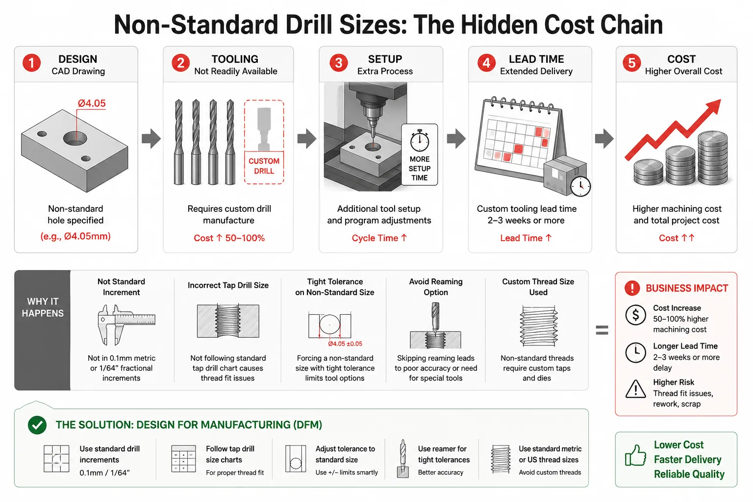

Few machined features earn their place as quietly as the counterbore. It answers a problem that turns up on nearly every assembly: a bolt head sitting proud of the face, catching on whatever slides past it, or keeping two parts from closing flat against each other.
This guide covers what the feature is, how it differs from countersinking and spotfacing, the situations that justify the second machining operation, the way it should appear on a drawing, and the sizing rules our engineers apply before a part is cut.
What a Counterbore Actually Is
A counterbore is a stepped hole. A cylindrical pocket with a flat floor is cut on the same axis as a smaller hole beneath it, so the two features share one centerline. The wider pocket swallows the head of a bolt, cap screw or similar fastener, while the narrower hole below takes the shank or the thread.
Two details of its geometry set it apart from other recessed holes. Its sidewalls stand at 90° to the surrounding face, and its floor is flat rather than tapered. A countersink, by contrast, is a cone — only a conical head seats correctly inside one. Put simply, a counterbore hides a cylindrical head and a countersink hides a tapered one.
- Counterbore diameter — cut a little wider than the fastener head so the head drops in without interference.
- Counterbore depth — deep enough to bury the head completely; the depth is measured to the floor, not to the shoulder where the cutter breaks in.
- Pilot hole — drilled to the fastener's shank or thread size and held coaxial with the pocket above it.
- Drawing symbol — a counterbore is called out with the ⌴ mark.
Counterbore vs Countersink vs Spotface
Four features are easy to confuse on a print because they all create some form of recess around a hole. What separates them is the shape of the recess and the job it performs.
| Feature | Geometry | What it does | Wall angle | Symbol |
|---|---|---|---|---|
| Counterbore | Cylindrical pocket, flat floor | Recesses a cylindrical head flush with the surface | 90° | ⌴ |
| Countersink | Conical recess | Seats a flat-head screw below the surface | 82° or 90° cone | ⌵ |
| Spotface | Shallow flat circular face | Creates a level seat for a washer, nut or gasket | 90° | ⌴ with shallow depth |
| Through hole | Bore passing through the part | Clearance for a fastener or a moving part | N/A | None |
| Blind hole | Stops inside the material | Locating, tapping or partial engagement | N/A | None |
Spotfacing deserves its own line because it is so often mixed up with counterboring. Both leave a flat floor with square walls, but a spotface only has to be deep enough to clean up the surface — usually a millimetre or less — whereas a counterbore has to be deep enough to hide the head. The same symbol serves both on a drawing, so the depth value is what tells the machinist which feature is intended.
When the Extra Machining Pays for Itself
A counterbore means a second operation on every hole, so it has to justify its cost. These are the cases that come up again and again when we review drawings.
The face has to stay clear
Whenever something slides, stacks or seals against a surface — drawer runners, mating plates, sensor mounts — a protruding head turns into an obstruction. Recessing the fastener keeps the face usable and leaves the assembly looking finished rather than improvised.
The joint carries real load
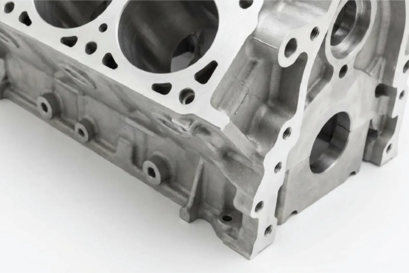
High loads call for large fasteners. Machinery frames, suspension hardware and engine blocks are all built around substantial bolts whose heads would intrude on the geometry around them. A counterbore gives that head somewhere to sit without shortening the grip length.
Position and depth have to be controlled
Aerospace fittings and precision instruments need each fastener seated in a known place, at a known depth, with predictable preload. The flat floor gives the head a repeatable bearing face, which is what keeps alignment and load distribution consistent from one part to the next.
The face has to seal
Gasket joints and PCB standoff patterns need an uninterrupted mating surface. A raised head either opens a leak path or lifts the parts apart, so keeping the surface clean matters as much as the fastener choice itself.
A protruding head is a hazard
Interiors, furniture and anything within reach of hands or moving parts are better off with heads below the surface. Recessed fasteners remove snag points and sharp edges from the finished product.
The fastener family requires it
Socket head cap screws, fillister head screws, washers, o-rings, gaskets and dedicated counterbore screws are all designed around a flat recessed seat rather than a conical one.
Where Counterbores Show Up in Production
| Industry | Typical parts | What the counterbore delivers |
|---|---|---|
| Automotive | Engine blocks, suspension brackets, transmission housings | Bolt heads sink below sealing faces, so the joint holds torque and assembly stays quick |
| Aerospace | Landing gear fittings, engine mounts, airframe brackets | Flush fasteners cut drag and keep the load path running through the structure |
| Electronics | PCB standoffs, enclosure lids, device internals | Clearance for stacked boards and a flat internal envelope |
| Industrial machinery | Structural frames, machine bases, heavy-duty joints | Room for large fasteners and a rigid connection between members |
| Furniture and consumer products | Visible hardware, sliding components, hinged panels | A clean exterior with no exposed head to catch on clothing or hands |
Reading and Writing the Callout
A counterbore callout has to answer three questions: how wide the pocket is, how deep it goes, and what lies underneath. The convention is to lead with the symbol, then the pocket diameter, then its depth, and to call out the pilot hole separately.
- Symbol and size — ⌴ 11 mm × 6.8 mm describes a pocket 11 mm across and 6.8 mm deep, with the pilot hole dimensioned on its own.
- Top view — pocket and pilot appear as two concentric circles.
- Section view — the same feature reads as a stepped profile with a square internal corner where the wall meets the floor.
- Depth reference — note whether the stated depth covers the pocket alone or the full feature, so nobody has to guess where the measurement starts.
Sizing Rules and Tolerance Budget
The values below are the starting point our engineers use when a drawing leaves a counterbore open to interpretation. Every one of them can be tightened, but each step tighter adds cost, so it should follow a real functional need rather than habit.
| Parameter | Rule of thumb | Why it matters |
|---|---|---|
| Pocket diameter | Head diameter + 0.1–0.2 mm | Enough clearance for the head to enter freely without wandering off centre |
| Pocket depth | Head height + 0.5–1.0 mm | The extra margin absorbs the corner radius left by the cutter |
| Tolerance | ±0.05 mm general, ±0.02 mm precision | Tighter numbers slow the process down; save them for interfaces that truly need them |
| Floor finish | Ra 3.2 µm standard, Ra 1.6 µm painted, Ra 0.8 µm optical | Finer floors cost more, so specify the finish the seat actually needs |
| Material around the pocket | At least one pocket diameter of wall | Thin walls around a recess are a common cause of cracking and distortion |
Material, Tooling and Inspection
Almost any machinable material can take a counterbore. Aluminum, brass and engineering plastics cut quickly with standard tooling; stainless steel, titanium and other work-hardening alloys need slower speeds, a rigid setup and enough coolant to keep heat out of the cut. In softer materials the priority shifts the other way — the risk is a burred edge or a floor that tears rather than machines cleanly.
The sequence on the shop floor rarely varies. The pilot hole is drilled first, and the pocket is cut in the same setup so both features keep a shared centerline. A counterbore cutter with a pilot pin is the fast route for standard sizes; an end mill is used for non-standard diameters or where the floor has to be exceptionally flat.
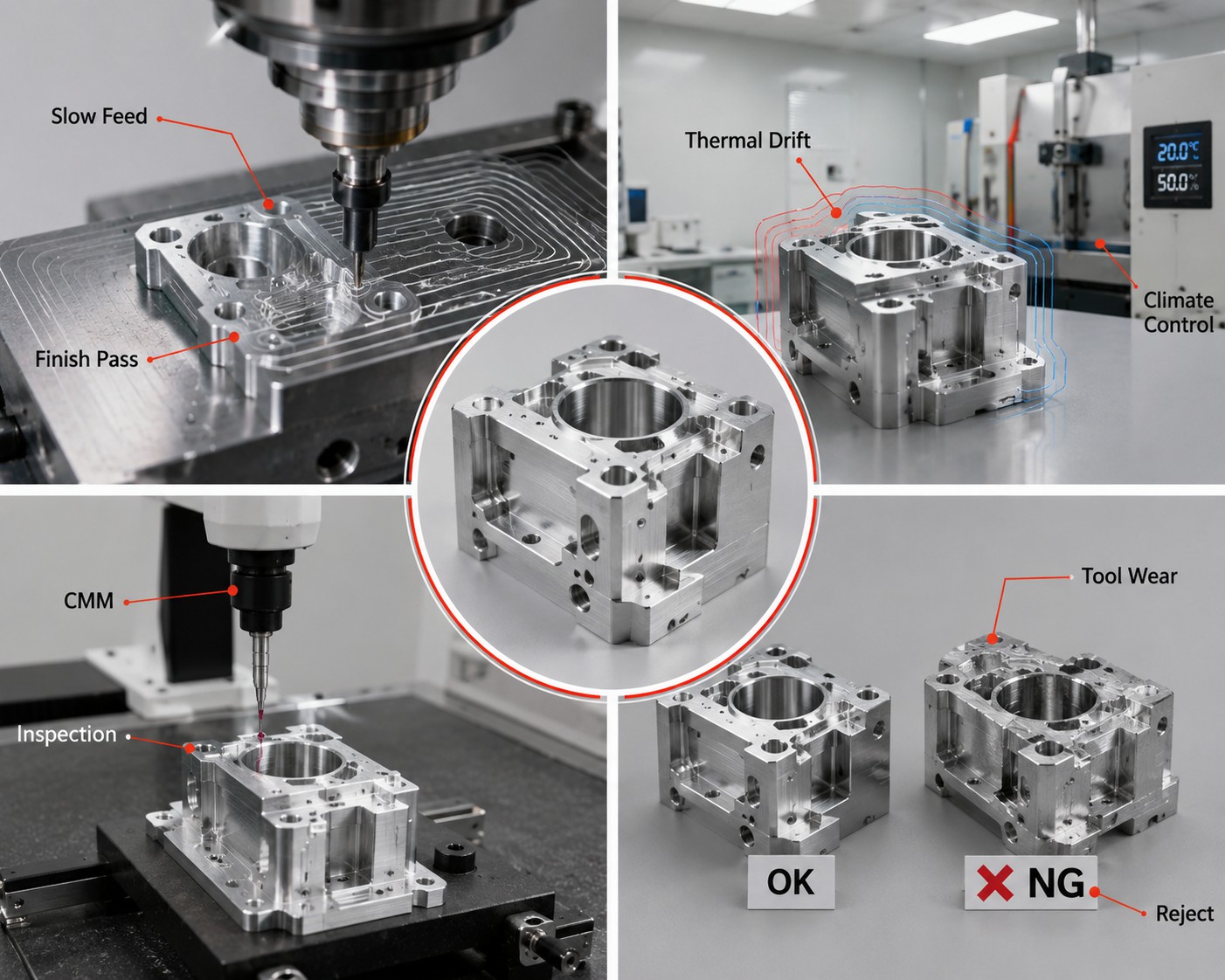
Verification is dimensional, not visual. Calipers or a bore gauge confirm the diameter and the pocket depth, and a CMM is used where concentricity between pocket and pilot has to be proven rather than assumed. Floor finish is checked whenever the feature seats a washer, a gasket or an o-ring.
Design Mistakes That Raise the Price
- Tolerancing the pocket tighter than the assembly needs. A counterbore that only hides a head does not need a precision position callout; adding one increases inspection and scrap cost for no functional gain.
- Leaving too little material around the pocket. A deep recess near an edge or a thin web invites cracking during machining and distortion after it.
- Cutting the pocket and the pilot in separate setups. Two setups means two datums, and the features drift out of concentricity as a result.
- Specifying counterbores where a plain hole would do. Each one is another operation, so unused features are pure cost.
- Leaving the depth reference undefined. If the note does not say whether the depth includes the cutter's corner radius, the part can be rejected on a matter of interpretation.
Quick Reference by Use Case
| Use case | What the counterbore buys you |
|---|---|
| Flush mounting | A surface that stays clear, safe and visually clean |
| High-strength joints | Room for large fasteners and a connection that holds |
| Precision assemblies | Repeatable seating, alignment and depth control |
| Sealing faces | Even compression on the gasket, with no leak path around a raised head |
| Product appearance | Hardware hidden below the surface for a finished look |
| Sliding or stacked parts | Nothing catches, and mating parts close flat |
Counterbore Holes at SHBD Metal
Counterbored holes come off our CNC mills and drills inside the same setup as the surrounding features, so diameter, depth and the relationship between pocket and pilot are all held in one fixturing. Send a 2D drawing or a 3D model and we return a quote with the machining sequence, the tolerances we intend to hold, and any feature we would change before cutting metal.
The feature sits alongside the rest of our hole-making capability on the CNC machining service page, and the materials we run it in are listed in the materials library. Every batch is inspected under our quality system, with dimensional records kept against the drawing revision.
Have a part with counterbored holes?
Get Instant QuoteFAQs
What is a counterbore hole, in plain terms?
It is a cylindrical pocket with a flat floor cut into a part so a fastener head can sit level with or below the surface. A narrower hole continues along the same axis to take the shank or the thread.
How should a counterbore be dimensioned?
Give the symbol, then the diameter and depth of the pocket, then the size of the pilot hole. The pocket has to be wider than the head and deep enough that the head clears the surface completely.
How is the pocket produced in metal or plastic?
Clamp the workpiece so it cannot move, choose a counterbore tool matched to the required size, keep the tool aligned with the pilot already in the part, then feed to the specified depth. Check the floor for a clean finish and confirm the depth before the part leaves the machine.
Can a counterbore be modelled in CAD software such as SolidWorks?
Yes. The Hole Wizard includes a counterbore type: select the face, choose Counterbore, enter the diameter and depth, then set the pilot size and placement before confirming the feature.
When is a countersink the better choice?
When the screw has a conical head. Flat-head and countersunk screws need a cone to seat properly, and a counterbore with a flat floor will not hold them.