Standard injection molding holds ±0.1 mm on most dimensions. For parts that snap together, seal against fluid, or mesh with gears, that is not good enough. Precision injection molding targets ±0.02 mm to ±0.05 mm — but the number on a drawing is only half the story. The other half is whether the part can hold that tolerance across an entire production run.
This guide covers what precision molding actually requires: the tolerances you can realistically expect by material, the process controls that keep dimensions stable, the tooling decisions that define what is possible, and when paying for precision makes sense versus when it does not.
What Is Precision Injection Molding?
Precision injection molding is not a different process from standard injection molding. It uses the same fundamental sequence: melt plastic, inject it into a mold cavity, cool, eject. The difference is in how tightly every variable in that sequence is controlled.
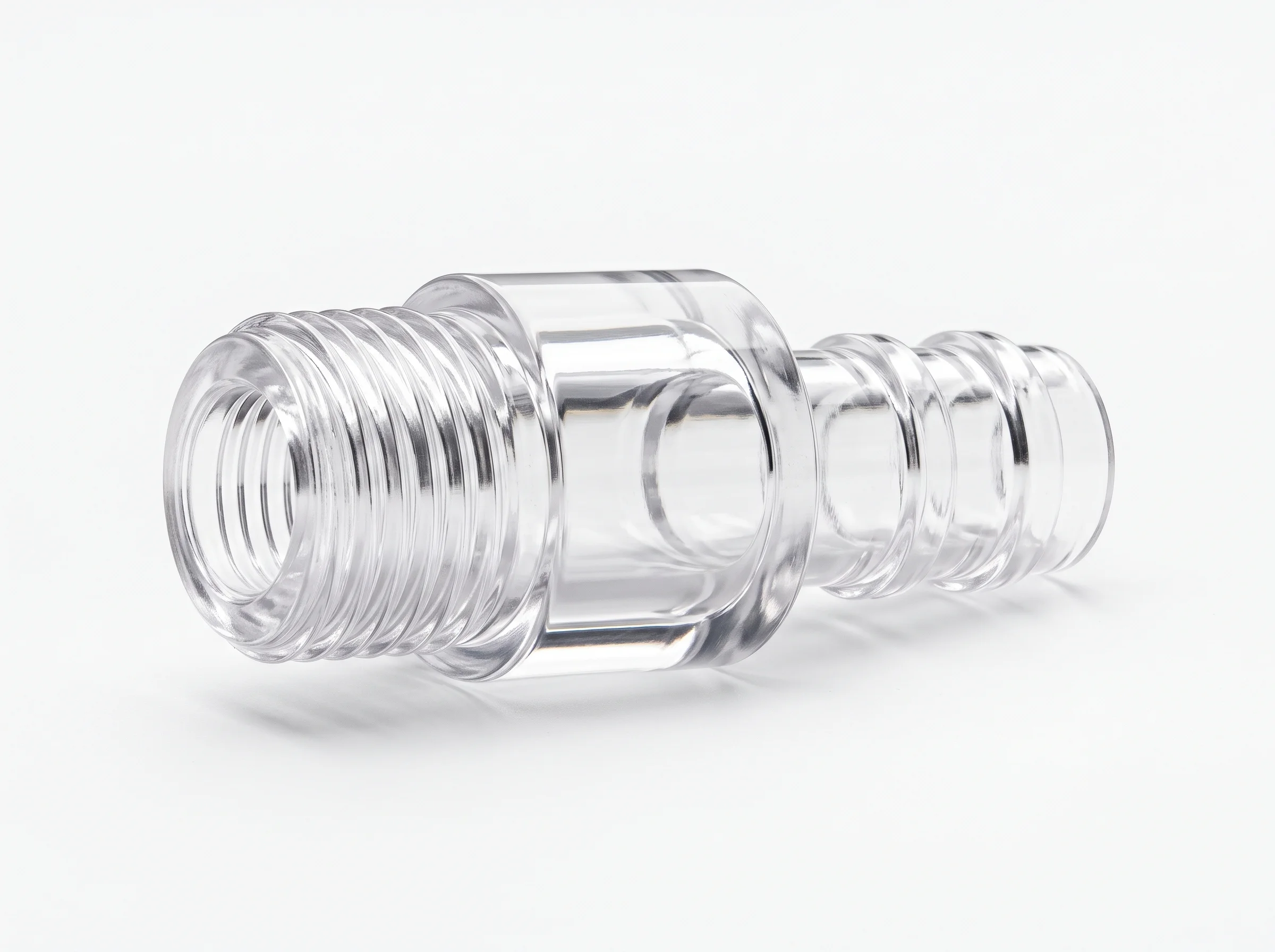
Four areas separate precision production from standard:
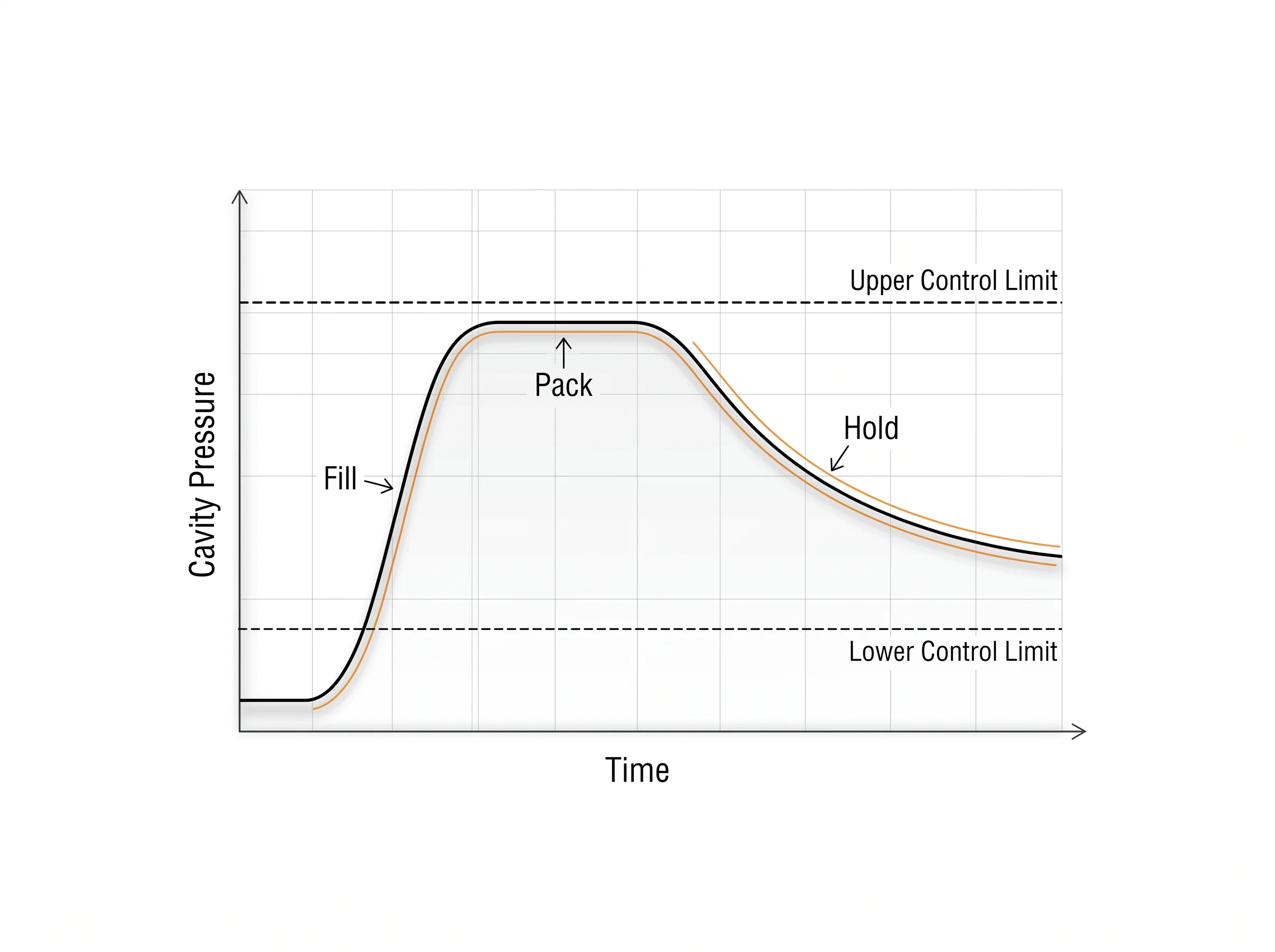
Pressure control. Precision molding uses closed-loop injection pressure regulation. The machine monitors cavity pressure in real time and adjusts fill speed, pack pressure, and hold time to keep each shot within a defined process window. A standard setup might run on timer-based control alone — open loop, no cavity feedback.
Mold alignment. Precision tools are built with tighter cavity machining tolerances, typically within ±0.01 mm on the steel itself. Ejector pin clearance, slide fit, and parting line flatness all get tighter than a standard production mold. The goal is to eliminate any source of dimensional variation that is not the plastic itself.
Real-time monitoring. Every shot in a precision run generates process data: cavity pressure curves, melt temperature, cooling rate, injection velocity. Statistical process control tracks these parameters against upper and lower control limits. When a parameter drifts, the operator catches it before parts go out of spec — not after a quality inspection catches the scrap.
Temperature stability. Melt temperature, mold temperature, and barrel zone temperature are all maintained within narrow bands — often ±1°C or tighter. Standard molding might tolerate ±5°C swings. For materials like PEEK or LCP, where viscosity changes sharply with temperature, those narrow bands are the difference between in-spec and scrap.
The real definition of precision is not the tolerance number on one measurement. It is dimensional repeatability across thousands of shots. A shop that hits ±0.02 mm on one sample but drifts to ±0.08 mm by the end of the shift is not doing precision molding — regardless of what the first article inspection report says.
Precision Injection Molding Tolerances
Tolerance Standards
The two primary references for injection molding tolerances are ISO 20457 and the SPI (Society of the Plastics Industry) classifications. Neither is a guarantee — both are guidelines that depend on material, geometry, and process control.
SPI divides tolerances into “commercial” and “fine” grades. ISO 20457 defines tolerance classes from coarse to precision. In practice, most shops define their own achievable range based on their equipment and quality system.
Achievable Tolerances by Material
The single largest factor in achievable tolerance is the material’s shrinkage rate. Every plastic shrinks as it cools. The amount and consistency of that shrinkage sets the floor for what is dimensionally possible.
| Material | Shrinkage Rate | Commercial Tol. | Precision Tol. | Notes |
| ABS | 0.4–0.7% | ±0.10 mm | ±0.05 mm | Low, predictable shrink. Good baseline. |
| PC | 0.5–0.7% | ±0.10 mm | ±0.05 mm | Dimensionally stable when dry. Moisture in resin causes splay and dimensional shift. |
| POM (Delrin) | 1.8–2.2% | ±0.15 mm | ±0.05 mm | High shrink but very consistent. Achievable with well-vented tooling. |
| PA66 (Nylon) | 0.8–1.5% | ±0.20 mm | ±0.10 mm | Hygroscopic. Post-mold moisture absorption causes 0.5–1.0% growth over 24 hours. Measure after conditioning. |
| PA66 GF30 | 0.3–0.6% | ±0.10 mm | ±0.05 mm | Glass fill reduces shrinkage. Weld line strength drops — gate placement critical. |
| PEEK | 0.4–0.6% | ±0.10 mm | ±0.05 mm | Requires 360–400°C barrel temperature. Hardened steel tooling only. High melt viscosity. |
| PPS | 0.6–1.0% | ±0.10 mm | ±0.05 mm | Low moisture absorption. Good for tight-tolerance parts in chemical environments. |
| PP (Unfilled) | 1.2–1.8% | ±0.20 mm | ±0.10 mm | High, anisotropic shrinkage. Avoid tight tolerances on long flow paths. |
| LCP | 0.1–0.3% | ±0.05 mm | ±0.02 mm | Near-zero shrink. Best-in-class for micro-precision. Requires high mold temperatures. |
What Affects Tolerance
Beyond material shrinkage, several factors push tolerances wider:
Part geometry. Thick-to-thin transitions create differential cooling rates and uneven shrinkage. A part with uniform wall thickness will hold tighter tolerances than one with a 6 mm boss next to a 1 mm wall.
Parting line position. Any dimension that crosses the parting line adds mold-half alignment error on top of material shrinkage. Critical dimensions should stay on one side of the parting line when possible.
Cavity count. A single-cavity tool is the easiest to control. A 16-cavity tool with unbalanced filling will push some cavities outside the precision window — even if the average meets spec.
Flow length. Long flow paths mean larger pressure drops and more shrinkage variation from gate to end-of-fill. The tighter the tolerance, the shorter the practical flow length.
The Tolerance Ceiling
There are limits that no amount of process control can overcome. A ±0.01 mm tolerance on an unfilled PP part with a 200 mm flow length is not achievable — not because the molder is not good enough, but because the material physics do not allow it.
When a part genuinely needs sub-±0.02 mm tolerances, injection molding may not be the right process. CNC machining from solid stock or secondary machining operations on molded blanks become the practical options.
Specifying Tolerances on Drawings
Do not tolerance every dimension on the drawing. Identify the 3–5 dimensions that are functionally critical — the ones that affect assembly, sealing, or performance — and tolerance those tightly. Leave the rest at commercial grade.
Communicate Cpk requirements for critical dimensions. A Cpk of 1.33 means the process spread fits within the tolerance band with some margin. A Cpk of 1.67 means it fits comfortably. Most precision molders target Cpk ≥ 1.33 on critical dimensions.
Materials for Precision Injection Molding
Material choice sets the floor for what is achievable. Before optimizing tooling or process parameters, confirm the material itself can deliver the required dimensional stability.
Material Properties That Drive Precision
Shrinkage rate and consistency. A low shrinkage rate helps, but consistency matters more. POM shrinks at nearly 2%, but it shrinks predictably. A material with 0.5% average shrink that varies by ±0.2% shot-to-shot is worse than a material with 2% shrink that varies by ±0.1%.
Moisture absorption. Nylon absorbs moisture from the air after molding and grows dimensionally. A PA66 part measured at ±0.05 mm right off the press may be ±0.12 mm 24 hours later. If the application involves humidity, specify measurement after conditioning.
Thermal expansion. Parts that operate across a temperature range need to account for thermal expansion. A PEEK part going from room temperature to 200°C will expand more than a steel housing around it — the tolerance analysis needs to include the operating temperature range.
Fillers and reinforcement. Glass fiber, carbon fiber, and mineral fillers reduce shrinkage and improve dimensional stability. The trade-off: they make the material more abrasive (shorter tool life), create anisotropic shrinkage (different shrinkage parallel vs. perpendicular to flow), and reduce weld line strength.
Amorphous vs Semi-Crystalline
Amorphous materials (ABS, PC, PS, Acrylic) shrink less and more uniformly than semi-crystalline materials (PA, POM, PP, PEEK). For the tightest tolerances with the least process complexity, start with an amorphous grade.
Semi-crystalline materials shrink more but can still achieve precision with proper process control and tooling. The key: maintain consistent mold temperature and cooling rate so the crystal structure forms the same way every shot.
When Glass-Filled Grades Help
Adding 30% glass fiber to PA66 cuts shrinkage from 0.8–1.5% to 0.3–0.6% — a meaningful improvement for dimensional control. But glass-filled grades come with costs:
- Weld line strength drops 30–50% compared to unfilled. Gate locations need to account for this.
- Mold wear accelerates. Hardened steel inserts are recommended.
- Surface finish degrades. Glass fibers create a matte, slightly textured appearance.
Material Selection Decision Table
| Requirement | Recommended Material | Why |
| General precision, moderate cost | ABS or PC | Low shrink, predictable, wide availability |
| High temperature + precision | PEEK or PPS | Dimensional stability at elevated temperatures |
| Micro-precision, near-zero shrink | LCP | Lowest shrinkage of any injection moldable thermoplastic |
| Toughness + precision | PC/ABS blend | Combines PC stability with ABS processability |
| Chemical resistance + precision | PPS or POM | PPS for aggressive chemicals, POM for fuels and solvents |
| Medical device precision | PC, PEEK, medical-grade ABS | Biocompatibility + dimensional stability |

Process Control in Precision Injection Molding
A precision-capable machine is not the same thing as precision production. The machine is the starting point. The process control system — how parameters are monitored, adjusted, and documented — is what keeps parts in spec across the run.
Scientific Molding vs Conventional Molding
Conventional molding relies on machine settings: barrel temperature set to 250°C, injection pressure set to 100 MPa, hold time set to 8 seconds. If the part comes out looking good, the settings stay.
Scientific molding measures what the plastic actually experiences inside the cavity. Instead of “injection pressure at 100 MPa,” the metric is “cavity pressure at the gate reaches 40 MPa by 0.8 seconds into fill.” This shifts the reference point from what the machine is doing to what the plastic is doing.
The core tools:
Cavity pressure sensors. Piezoelectric sensors mounted behind ejector pins or directly in the cavity wall measure pressure in real time. The pressure curve — rise rate, peak, hold decay — tells you whether the cavity filled completely, whether packing was sufficient, and whether cooling progressed normally.
Closed-loop control. The machine controller adjusts injection velocity and pack pressure based on cavity sensor feedback. If the pressure curve for shot 127 deviates from the reference curve for shot 1, the controller corrects in real time — not after a quality check catches the problem.
Melt temperature consistency. Barrel zone temperatures alone do not guarantee melt temperature consistency. Screw recovery time, back pressure, and screw speed all affect shear heating. Precision molding monitors melt temperature at the nozzle and adjusts screw parameters to keep it within a narrow band.
Statistical Process Control (SPC)
SPC is the bridge between process data and part quality. For precision molding, it typically works like this:
- Define critical dimensions (3–5 per part).
- Set upper and lower control limits for those dimensions based on the tolerance band and the process capability target.
- Measure parts at defined intervals (e.g., every 50 shots) and plot the results against the control limits.
- When a measurement trend approaches a control limit — even if the part is still in spec — investigate and correct before out-of-spec parts are produced.
Cpk quantifies how well the process is performing. A Cpk of 1.0 means the process spread exactly fills the tolerance band. Cpk of 1.33 is the typical minimum for precision work. Cpk of 1.67 or higher means the process has comfortable margin.
The Real Difference: People and Systems
A precision molding operation is not defined by one expensive machine. It is defined by whether the production team:
- Logs every process parameter, not just the ones that changed
- Has a documented response plan for every out-of-control signal
- Measures critical dimensions on a schedule, not just when a problem is suspected
- Maintains mold condition proactively — cleaning vents, checking wear surfaces, verifying alignment — on a defined interval
Without this system, even the most advanced all-electric press will produce parts that drift across the run.
Mold Design for Precision Injection Molding
The mold is the single largest investment in a precision molding project. Tooling decisions made during mold design directly determine what tolerances are achievable — and what problems will appear 100,000 shots later.
Tool Steel Selection
Precision molds use hardened tool steel, not pre-hardened or aluminum. Common choices:
| Steel Grade | Hardness (HRC) | Best For |
| P20 | 28–32 | Low-volume (<100k shots), non-abrasive materials |
| H13 | 48–52 | High-volume production, glass-filled materials, good thermal fatigue resistance |
| S136 / 420 SS | 50–54 | High-polish surfaces, corrosion resistance, medical/optical parts |
| M390 | 56–60 | Maximum wear resistance, glass-filled engineering resins, high-volume precision |
Steel hardness matters for two reasons. First, harder steel resists the abrasive wear from glass-filled materials that gradually opens up cavity dimensions. Second, harder steel holds its shape through thermal cycling — each shot is a heat-cool cycle that can slowly warp a softer mold.
Cooling Design
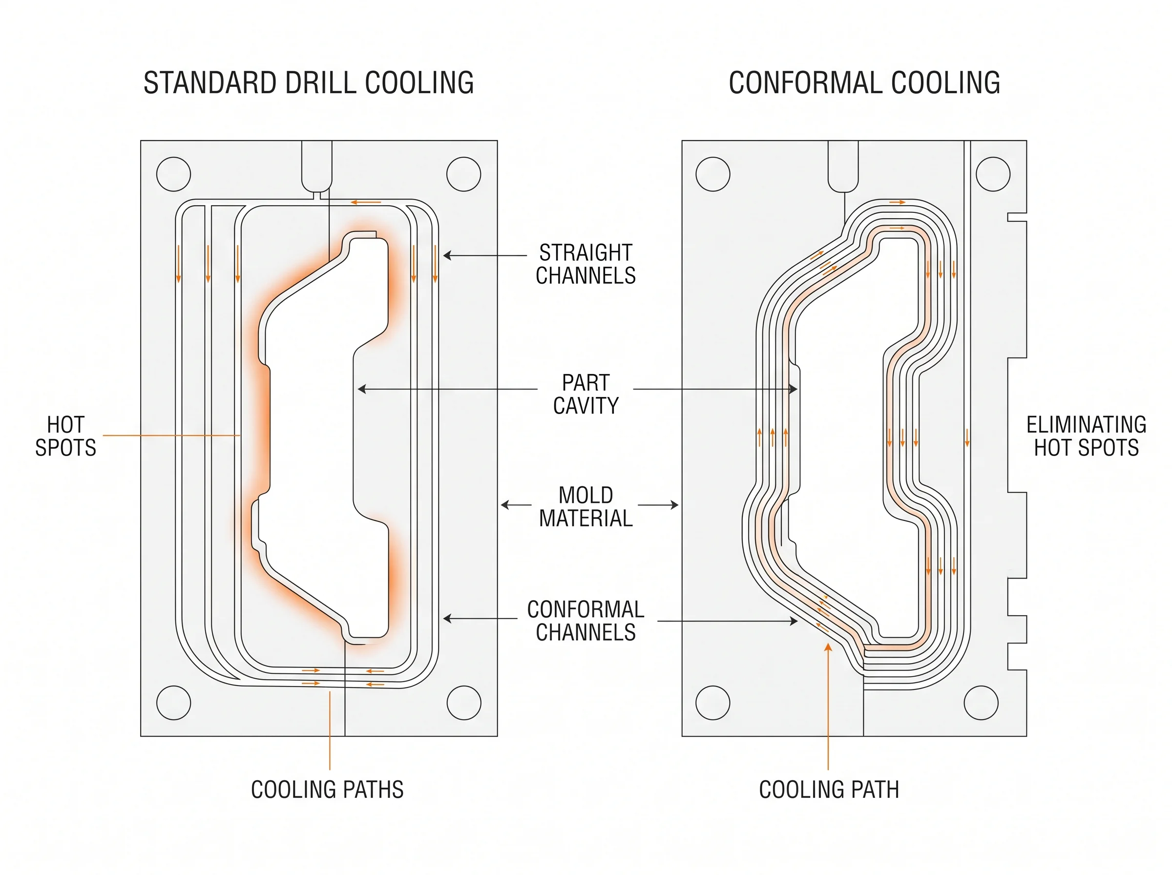
Cooling is not about speed. It is about uniformity. If one side of the cavity cools faster than the other, the part warps toward the hotter side. The tighter the tolerance, the more uniform the cooling needs to be.
Conformal cooling — cooling channels that follow the contour of the cavity instead of straight drilled lines — reduces hot spots and cuts cycle time. For precision parts with complex geometry, conformal cooling can be the difference between a warp-free part and one that needs secondary straightening.
Mold temperature control keeps the entire tool at a consistent temperature, shot to shot. For semi-crystalline materials like PEEK and POM, mold temperature directly controls the crystallization rate and therefore the final dimensions. A mold temperature swing of even 5°C between shots can produce measurable dimensional variation.
Gate Design and Runner Balancing
In a multi-cavity mold, every cavity must fill at the same rate, at the same pressure, and at the same temperature. That requires balanced runners — flow paths of equal length and cross-section to each cavity.
Gate type and location affect precision in two ways:
- Gate size controls fill rate and pack efficiency. A gate too small restricts flow and creates high shear, which heats the material locally and changes shrinkage. A gate too large slows solidification and extends cycle time.
- Gate location determines the flow pattern and therefore the shrinkage direction. For a rectangular part, gating at the center produces radial flow and uniform radial shrinkage. Gating at the edge produces directional flow and directional shrinkage — the dimension parallel to flow will shrink differently than the dimension perpendicular to flow.
Parting Line Considerations
Any dimension that crosses the parting line picks up the alignment error between mold halves. For a standard mold, that error might be ±0.03 mm. For a precision mold with taper locks and precision leader pins, it might be ±0.01 mm. Either way, it is additive to material shrinkage variation.
Critical dimensions should stay on one side of the parting line. When a dimension must cross it, the mold needs positive alignment features — taper locks, wedge locks, or precision interlocks — to minimize mold-half mismatch.
Tool Maintenance Schedule
Precision molds degrade differently than standard molds. The failure mode is not catastrophic — it is gradual dimensional drift. A mold that produced parts within ±0.05 mm at shot 1 may be producing parts at ±0.07 mm by shot 50,000, with no visible change to the tool.
A maintenance schedule for precision tooling includes:
- Vent cleaning every 10,000–25,000 shots
- Wear surface inspection at the same interval
- Dimensional verification of critical cavity features at 100,000-shot milestones
- Ejector pin clearance and alignment check every 50,000 shots
When Precision Injection Molding Is Worth the Cost
Precision molding costs more — in tooling, in cycle time, in material grade, and in inspection overhead. The question is whether the additional cost buys something the part genuinely needs.
What Drives the Cost Premium
Tooling. A precision mold with hardened steel, conformal cooling, balanced runners, and taper locks costs 30–60% more than a standard production mold for the same part geometry.
Cycle time. Precision molding runs slower. Longer fill times, controlled cooling rates, and more frequent quality checks all add seconds to each cycle. Over a 100,000-shot run, 3 extra seconds per cycle adds over 80 hours of machine time.
Material grade. Precision work often requires engineering resins (PEEK, PPS, LCP) that cost 5–20× more per kilogram than commodity grades (PP, ABS).
Inspection. SPC measurement, CMM verification, and first article inspection reports add labor cost that standard molding skips.
When Precision Is Mandatory
Sealing surfaces. A gasket groove or o-ring seat that is oversized by 0.05 mm leaks. Undersized by the same amount, it crushes the seal. Precision is not optional — it is a functional requirement.
Snap-fit assemblies. Snap-fit geometry depends on interference between two molded features. If the interference is too small, the assembly rattles. If it is too large, it breaks during assembly or needs excessive insertion force. The tolerance window is narrow.
Gear meshes and mechanical interfaces. A gear tooth profile that deviates by 0.03 mm from nominal changes the backlash and wear pattern. Over a gear train with four mesh points, the cumulative error can make the mechanism bind or skip.
Optical components. Lens mounts, light pipe interfaces, and sensor alignment features need tight positional tolerances. A 0.05 mm shift in the focal plane can be visible in the final image.
Medical device components. Syringe plungers, inhaler dose chambers, and surgical instrument interfaces have tolerances driven by regulatory requirements, not just functional ones. ISO 13485 certification requires documented process control that standard molding shops may not maintain.
When Standard Molding Is the Smarter Choice
Cosmetic housings. An enclosure that snaps together does not need ±0.05 mm on every surface. Commercial tolerances and good design for assembly will usually suffice.
Non-critical internal features. Internal ribs, bosses for self-tapping screws, and clearance pockets rarely need precision. Tolerancing them tightly adds cost with no functional benefit.
First-run prototypes. Before committing to precision tooling, run a prototype mold at commercial tolerances. Test the assembly. Identify which dimensions actually need tightening — the list is usually shorter than you think.
Low-volume runs. Precision tooling amortized over 5,000 parts costs dramatically more per part than over 500,000. If the annual volume is low, consider CNC machining or a standard mold with secondary machining on critical features.
The Over-Specification Trap
The most common and expensive mistake in injection molding is over-specifying tolerances. Every dimension called out at ±0.05 mm instead of ±0.10 mm adds cost to the tool, the cycle, and the inspection plan — even on features where the extra precision does nothing for function.
Before sending a drawing to a molder, ask three questions:
- What happens if this dimension is 0.05 mm over? 0.05 mm under?
- Is the consequence a functional failure or just a cosmetic imperfection?
- Can the assembly tolerate the variation, or can a design change eliminate the tight tolerance requirement?
The answer to the third question often saves more money than negotiating the molding price.
Conclusion
Precision injection molding is a systems problem — not a machine problem, not a material problem, not a tooling problem alone. The tolerance on the drawing is only achievable when all three are aligned.
The material must have low, consistent shrinkage. The mold must be built to hold dimensions through hundreds of thousands of thermal cycles. The process must be monitored, measured, and adjusted in real time. And the inspection system must catch drift before it produces scrap.
For parts that seal, snap, mesh, or align with sub-0.05 mm requirements, precision molding is the right process — and worth the tooling premium. For parts where function tolerates commercial-grade variation, standard molding is the smarter economic choice.
If you are evaluating whether your part needs precision injection molding, upload your CAD file for a free DFM review and instant quote. The manufacturability analysis will flag tolerance risks, material fit issues, and process control requirements before you commit to tooling.
FAQ
ISO 9001 is the baseline for any quality-managed production. For automotive applications, IATF 16949 certification is typically required. For medical devices, ISO 13485 is the standard. Look for evidence of in-house CMM capability, documented SPC programs, and a mold maintenance tracking system — certificates alone do not guarantee precision capability.
Identify the 3–5 dimensions that are functionally critical and tolerance them tightly. Leave the rest at commercial grade. Include Cpk requirements for critical dimensions — a target of Cpk ≥ 1.33 is the typical minimum for precision work. Attach a note specifying measurement conditions (temperature, humidity, post-molding conditioning time) for hygroscopic materials like nylon.
Cpk 1.33 means the process spread fits within the tolerance band with some margin — roughly 4 sigma between the mean and the nearest tolerance limit. Cpk 1.67 means wider margin, roughly 5 sigma. For a ±0.05 mm tolerance, a Cpk 1.33 process may occasionally touch the limit; a Cpk 1.67 process stays comfortably inside. Medical and aerospace applications often require Cpk ≥ 1.67 on critical dimensions.
Precision tooling adds 2–4 weeks to a standard tooling timeline due to tighter cavity machining, conformal cooling channels, hardened steel processing, and more extensive dimensional verification before first shots. A standard production mold might ship in 4–6 weeks; a precision mold for the same part geometry typically takes 6–10 weeks. Rush schedules are possible but risk compromising the verification steps that make precision tooling worth the investment.
Usually not. Prototypes exist to validate form, fit, and function — not to confirm production-level Cpk. A standard mold or even a 3D-printed prototype can confirm the design before you invest in precision tooling. For low-volume production when tolerances are genuinely tight, CNC machining from solid stock may be more cost-effective than amortizing precision tooling across a small run. The transition point depends on part geometry and annual volume — a DFM review can help identify the right approach.
RapidDirect holds ISO 13485 and IATF 16949 certifications. The injection molding service includes mold flow analysis, precision tooling with hardened steel options, and full-process SPC with CMM inspection. For a precision project assessment, upload your CAD file for a free DFM report and instant quote.