Snap-fit joints are one of the simplest ways to connect parts without screws, adhesives, or tools. Instead of relying on separate fasteners, snap-fits use flexible features that bend during assembly and then spring back to hold components together. This makes them popular in parts like plastic enclosures, battery covers, consumer electronics, and appliance housings, and even pen caps, where quick assembly (and disassembly) matters.
Snap-fits work best when everything clicks. The shape of the joint, the material you choose, and the manufacturing method all influence how well it performs. A design requires careful consideration of geometry, assembly force, and long-term durability. A snap that works in injection molded polypropylene may fail if 3D printed with resin, and a design that assembles easily may not survive repeated use without proper analysis of material properties and testing.
This article goes over the basics of snap-fit joints, giving you an understanding of how a company like 3ERP uses plastic manufacturing technologies to fabricate these convenient connectors. It also includes basic design rules for different technologies, giving you a head start on your snap-fit designs.
What Is a Snap Fit Joint?
A snap-fit joint is a connector formed by interlocking features integrated into two parts. During assembly, one feature deflects elastically and then returns to its original shape to engage the mating part, creating retention without additional hardware.
The key features of a snap-fit joint include elastic deformation during assembly, tool-free engagement, integrated locking geometry, and the ability to form either releasable or permanent connections. These characteristics make snap-fits especially suitable for high-volume products where speed, simplicity, and reliability are essential.
In advanced applications, designers may use a shaped snap fit to control engagement force, feedback feel, or removal resistance.
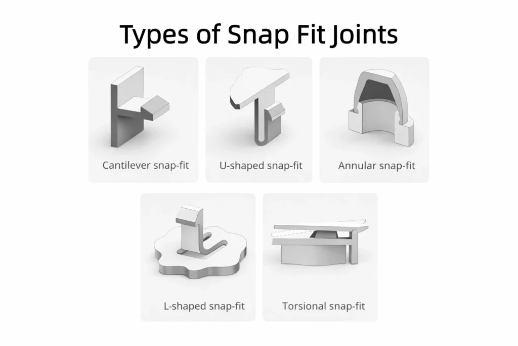
Snap-fits can take many forms. Some are releasable; others form a permanent snap joint. While the McGraw-Hill Dictionary of Engineering defines a “snap fastener” as a ball-and-socket style connector, real-world designs include cantilever beams, circular rings, torsional locks, and more complex geometries. As we will see, snap-fits can assume many forms.
Why Use Snap Fits?
Snap-fit joints are important in many engineering designs due to their convenience, ease of manufacturing, and freedom from separate fasteners like screws.
- Simplicity: Snap fits are designed into the two interlocking components themselves, without the need for a separate fastener, reducing assembly time and inventory required.
- Cost: Since they do not require a third component to join the two interconnecting pieces, snap-fits can be cheaper than other fastening techniques.
- Fast assembly: Most snap fits can be connected (and often disconnected) with a quick, user-friendly motion like a push or squeeze, making them ideal for parts that need to be regularly attached then detached. Power tools are not required.
- Versatile: Snap fits can be made multiple-use (releasable) or permanent, depending on the type of connection required.
- Appearance: Lack of fasteners gives a clean visual appearance, as the locking mechanism of a snap fit is typically embedded within one of the components.
Snap Fit Suitability Checklist
Of course, snap fits are not suitable for all applications. They increase design complexity, are vulnerable to breakage, and do not offer the same clamping load as other connections. With that in mind, the following checklist serves as a quick guide for when they should be used.
- Are accurate load and use-case conditions known so the snap-fit can be analyzed properly?
- Are part dimensions and tolerances controlled closely enough for consistent engagement between the two components?
- Is the packaging and access for assembly and service clearly understood?
- Is there enough development time available to design and validate the snap-fit?
- Does the supplier or organization have experience designing and molding snap-fit parts?
Common Types of Snap Fit Designs
Most snap-fit joints fall into one of three main categories, defined below. However, subtypes exist within these categories. Furthermore, some snap-fits are not easily classified, as they may require a mixture of bending and torsional forces during assembly.
Cantilever Snap Fits
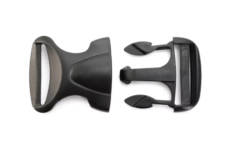
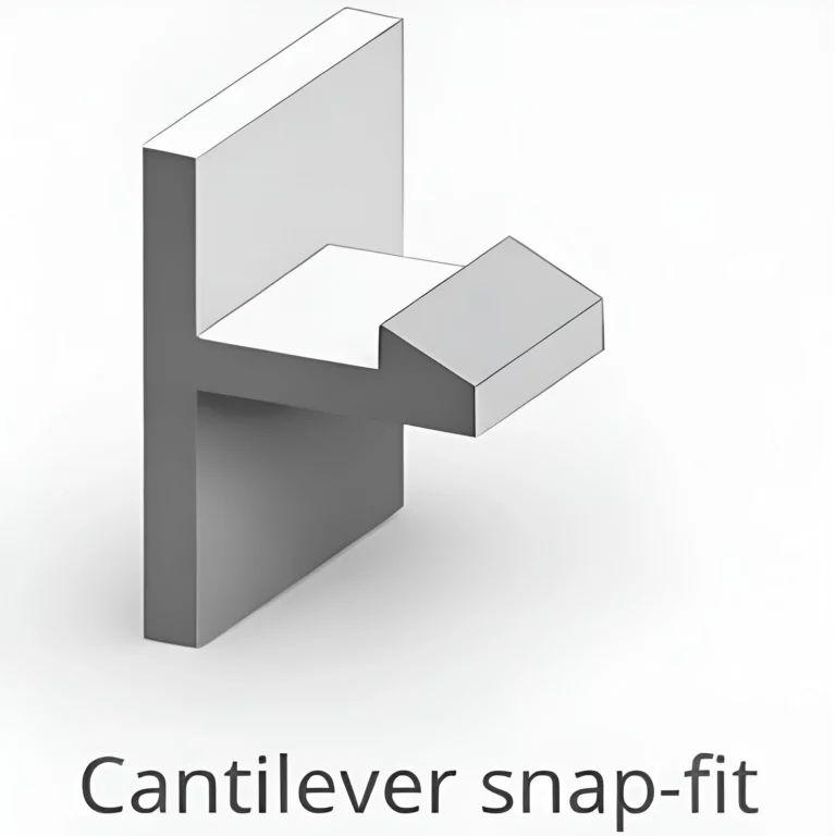
The most common snap-fit design is the cantilever. This consists of a flexible beam with a hook at one end that deflects during assembly before snapping into place. Multiple-use cantilever snap-fits usually have a lever or other device for detachment, but permanent snap-fits do not have this feature.
Example products with cantilever snap-fit joints include:
- Battery compartment lids for devices like remote controls and toys
- Electrical access panels
- Side-release plastic buckles
The ubiquity of these products creates a feedback loop where designers often default to the cantilever style of snap-fit joint, even when other styles may better suit the application.
Annular Snap Fits
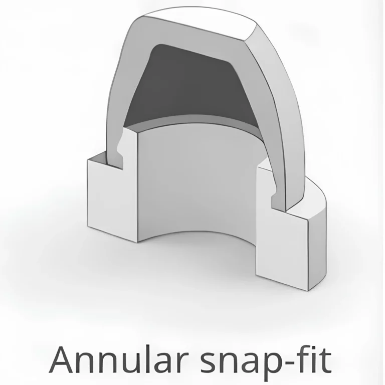
An annular snap joint connects concentric cylindrical features using radial deflection. A ball and socket joint snap-fit joint is a type of annular connection, and multiple-use annular snap-fits are more common than permanent ones.
These snap-fits only work if there is a degree of radial elasticity, which allows the inner ring to snap within the outer one. Over time, creep or stress relaxation may reduce retention force, which is one of the common issues designers must evaluate.
Example products with annular snap-fit joints include:
- Metal snap fasteners on clothing
- Lids on ball-point pens
- Caps on 35 mm film canisters
- LEGO bricks
Torsion Snap Fits
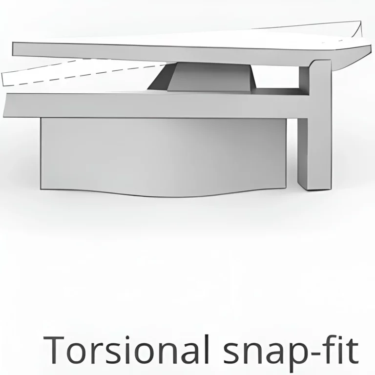
Torsional snap-fit joints are a less common variety that work by twisting during assembly instead of just bending. The part twists out of the way, then springs back to lock in place. Its strength depends on how stiff the twisting section is and how the locking shape is designed.
These sorts of snap-fits are useful when access for release is limited, when a low-profile lock is needed, or when the design needs a controlled “seesaw” motion to unlock the snap from the opposite side.
Manufacturing Methods
Injection molding is by far the most common manufacturing process used to make snap-fit joints. However, other plastic manufacturing techniques like 3D printing can be used, as can metal production methods like sheet metal stamping and cutting.
Injection Molding Snap Fits
Injection molding is the most common technique for mass production of plastic parts with snap-fit elements. Snap features can be molded directly into plastic parts, and the process is well suited to consumer products, housings, appliance parts, and automotive interior components.
Common snap-fit plastics for injection molding include polypropylene (PP), ABS, polycarbonate (PC), nylon (PA), and acetal (POM). Polypropylene in particular has very high strain capability. Nylon offers toughness and fatigue resistance for repeated use. ABS provides good stiffness and ease of molding for general applications, and polycarbonate offers higher strength but less flexibility.
Proper snap-fit design must account for strain limits, root radii, and long-term durability to avoid cracking or fatigue failure.
Molded Snap Fit Design Rules
- Keep deflection strain below the material limit: Design the snap so it flexes within the plastic’s safe stretch range; overstretching is like bending a paperclip too far and leads to cracks or permanent deformation.
- Use longer snap arms to reduce stress: Longer arms bend more easily and spread the load over a greater length, lowering the chance of breakage during assembly.
- Maintain uniform thickness and add a generous root radius (≈0.5–1× thickness): Even thickness distributes stress, while a smooth curve at the base prevents cracking where the snap meets the main part.
- Avoid sharp corners and abrupt transitions: Sharp edges concentrate stress and can start cracks, whereas smooth transitions let forces flow more evenly through the feature.
- Use a lead-in angle (≈30–45°) and a steeper retaining face: A sloped front helps parts snap together with less force, while a steeper back face keeps them securely locked once they are
- Provide enough clearance: Leave enough space for the snap arm to flex during assembly so it doesn’t jam or collide with nearby walls.
- Orient snaps for clean molding and avoid gates or weld lines at the root: Position the snap base where plastic fills and cools evenly so the joint forms strong and consistent.
CNC Machining Snap Fits
CNC machining is commonly used for prototypes, low-volume production, and functional testing of snap-fit joints. Snap features are cut from the solid plastic or metal workpiece rather than molded, so design rules and other considerations differ slightly. CNC machined snap-fits are often used in parts like engineering samples and short-run enclosures where mold tooling is not available yet.
Common plastics for CNC snap-fits include acetal (POM), nylon (PA), ABS, polycarbonate (PC), and HDPE. Acetal and nylon are especially suitable because they combine toughness with good fatigue resistance. ABS is easy to machine and good for general testing, while polycarbonate provides higher strength but requires conservative deflection.
Because machined parts lack molded fiber orientation and may have sharper internal corners from tooling limits, snap features are usually designed more conservatively than molded versions.
Machined Snap Fit Design Rules
- Keep deflection strain below the material limit and design more conservatively: Machined plastics lack the uniform fiber flow of molded parts, so design snaps to flex less and stay well within safe bending limits to avoid cracking.
- Use longer and slightly thicker snap arms than molded equivalents: Extra length reduces bending stress, and a bit more thickness adds strength to compensate for machining marks and material variability.
- Add large internal radii at snap roots: Rounded inside corners match typical cutter sizes and prevent sharp stress points where cracks could start.
- Avoid very thin or deep snap beams: Extremely slender features are hard to machine accurately and may result in warp, chatter, or breakage during cutting.
- Use a lead-in angle (≈30–45°) on the hook: A sloped front edge lets parts slide together with less force, reducing how far the snap must bend during assembly.
- Provide clearance for tool access and snap movement: Leave room for cutting tools to reach the feature and for the snap arm to flex freely without hitting nearby geometry during assembly.
3D Printing Snap Fits
3D printing is now widely used for prototyping, functional testing, and short-run production of snap-fit joints. Snap features can be printed directly into parts with greater design freedom than other methods. For example, undercuts are easily achieved.
This allows rapid iteration and evaluation of the joint ahead of its manufacture using other techniques. 3D printing is especially useful for early-stage product development and testing when tooling for injection molding is not yet justified. However, because printed parts are weaker and more anisotropic than molded parts, snap-fit features must be designed conservatively and tested carefully.
Common materials for printed snap-fits include SLS or MJF nylon (PA12), PETG and ABS filament, and tough SLA resins. SLS and MJF nylon provide the best combination of strength, flexibility, and fatigue resistance for working snap joints. FDM materials like PETG and ABS can work for basic testing but are more sensitive to print orientation and layer adhesion. Only tough resins should be used, as they are less brittle than regular photopolymerization materials.
3D Printed Snap Fit Design Rules
- Keep deflection strain well below the material limit and design conservatively: 3D printed plastics are weaker and more directional than molded ones, so limit how far snaps bend to avoid cracking or permanent deformation.
- Make snap arms longer and thicker (often 1.2–2× molded thickness): Extra length lowers bending stress and added thickness compensates for reduced strength and layer bonding in printed parts.
- Taper cantilever beams toward the tip: A gradual narrowing spreads strain more evenly along the arm so stress doesn’t concentrate at the base.
- Use large root radii and smooth transitions: Rounded bases and gentle shape changes reduce stress buildup and help prevent layers from splitting apart.
- Orient parts so layers run along the snap arm length: Aligning print layers with the direction of bending improves strength and reduces the chance of the snap breaking between layers.
- Use lead-in angles (≈30–45°): A sloped hook face helps parts slide together with less force, reducing how much the snap must flex during assembly.
Snap Fits From Sheet Metal
Sheet metal snap features are used in stamped or formed metal parts where elastic deflection of a tab, ring, or spring feature provides retention. They are common in hardware such as annular snap fasteners, spring tabs, and push-in clips. Compared with plastic snaps, metal snaps rely on elastic bending of thin sections and are designed to stay well within the material’s elastic range to avoid permanent set.
Typical sheet metals for snap-fits include spring steel, stainless steel, phosphor bronze, and aluminum alloys with good fatigue performance. Heat treatment or work hardening is often used to achieve the required spring properties.
Because sheet-metal snaps are formed rather than molded, geometry must suit stamping, laser cutting, or forming operations. Additionally, feature design must account for bend radii, grain direction, and allowable elastic strain. Metal snap features generally tolerate less strain than plastic ones.
Sheet Metal Snap Fit Design Rules
- Keep elastic strain within the safe limit: Design tabs so they bend only within the metal’s spring range.
- Use longer tabs to reduce stress: Longer features flex more easily and spread the bend over a greater length, lowering the chance of fatigue or breakage.
- Use bend radii suited to thickness (typically ≥1× thickness): A larger bend radius reduces stress at the fold and helps prevent the metal from thinning or cracking at the bend line.
- Avoid sharp internal corners and notches: Sharp features concentrate stress and can start cracks, especially after repeated flexing; smooth transitions improve durability.
- Orient bends relative to grain direction: Bending across the rolling grain usually improves fatigue life, while bending with the grain can make cracks more likely over time.
Snap Fit Joints Vs Threaded Fasteners
| Feature | Snap-fits | Threaded fasteners |
|---|---|---|
| Parts required | Fewer parts; fastener integrated into plastic | Additional hardware (screws, nuts, washers) |
| Assembly time | Faster assembly, suitable for mass production | Slower assembly |
| Tools needed | Usually none | Requires tools or drivers |
| Appearance | No visible fasteners; clean exterior | Visible fasteners often present |
| Adjustability | Typically no adjustment after assembly; disassembly possible unless permanent snap joint | Can be adjusted, retightened, and disassembled |
| Strength source | Limited by parent material strength | Fastener strength largely independent of plastic |
| Tolerance sensitivity | Requires tight dimensional control | More tolerant of variation |
| Cost | Higher design and development effort, and higher per part | Lower initial design cost and part cost |
| Assembly feedback | Can provide tactile “snap” feedback | No inherent feedback |
| Clamp load | Little or none | Provides clamp load between parts |
| Risk to plastic | No screw-induced cracking | Clamp load may crack plastic bosses |