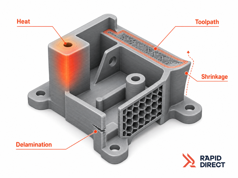
Shifting a component’s design framework toward additive manufacturing (AM) requires a radical departure from traditional subtractive engineering heuristics. Transitioning your CAD modeling mindset to master how to design for 3d printing is not an exercise in adjusting basic software slider settings. Instead, it demands a data-driven calculation of volumetric heat accumulation, macro toolpath geometry, and polymer shrinkage mechanics.
Failing to implement professional 3d printer design guidelinesduring the initial product design and rapid prototyping stages inevitably manifests as severe component warpage, catastrophic layer delamination, and out-of-tolerance dimensions that ruin multi-part mechanical assemblies. For Senior Mechanical Engineers, Product Designers, and NPI Sourcing Managers, understanding these physical boundaries is the only pathway to mitigating operational expenses (OpEx) and controlling part quality before committing to industrial-grade additive production.
Geometric Boundary Conditions: Volumetric Heat Control and Wall Heuristics
A highly accurate, optimized wall thickness is the absolute cornerstone of a printable, structurally sound additive component. In an industrial ecosystem, engineers must completely abandon consumer-level generalities and strictly design around process-specific thermodynamic boundaries.
The Core Cooling Dilemma
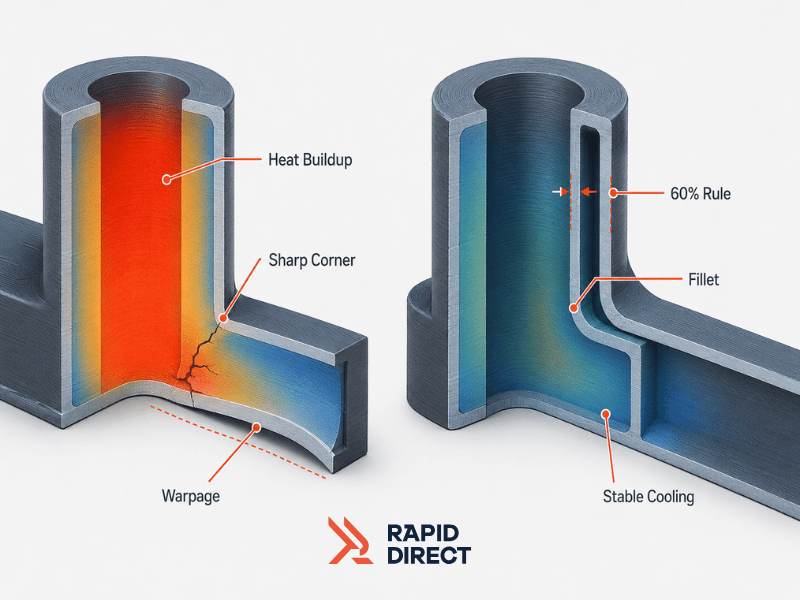
When a mechanical engineer models an excessively thick, dense, or solid intersection, the core of that geometry acts as a massive thermal insulator. During powder-bed fusion processes, such as Selective Laser Sintering (SLS) or Multi-Jet Fusion (MJF), high-energy lasers or fusing lamps deliver rapid thermal energy. The exterior skin of the part solidifies almost instantly against the cooler surrounding powder, while the dense internal core remains molten for an extended duration.
This severe, uneven cooling gradient generates aggressive internal tensile stresses. As the part cools to ambient temperature, these forces release, causing structural twisting, severe outer skin warpage, inner microstructural voids, and dimensional cracking along weak layer lines.
The Proportional Scaling Rule
To eliminate thermal stress concentrations and warpage at intersections, the wall thickness of any secondary or adjacent feature must not deviate by more than 60% of the primary wall thickness. Maintaining this proportion stabilizes the thermal crystallization gradients of the polymer during solidification.
Furthermore, sharp 90-degree internal corner vertexes must be completely eliminated from the design. Replacing them with a generous radius fillet or internal curve evenly distributes mechanical load forces and prevents catastrophic crack propagation when the part is subjected to functional cyclic stress.
Slicing Geometry and Toolpath Optimization for Industrial FDM
When executing how to design 3d print models for industrial Fused Deposition Modeling (FDM), your CAD dimensions cannot be arbitrary; they must strictly map to the hardware’s physical extrusion nozzle diameter.
If an engineer inputs a wall thickness that is not an exact integer multiple of the machine’s extrusion width, the slice engine triggers a severe toolpath conflict. For example, utilizing a standard 0.4mm industrial nozzle to print a 1.0mm wall forces the slicer to chart two clean outer perimeters
, leaving an empty, non-divisible 0.2mm air gap inside the core.
To seal this internal gap, the machine must execute thousands of rapid, micro-vibrational “zig-zag” maneuvers known as gap filling.
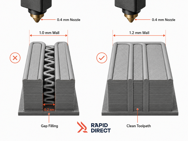
This unnecessary toolpath movement drastically inflates your machine-hour costs and cycle times (OpEx) while severely weakening the mechanical bond and layer adhesion of the shell. To maximize structural integrity and lower production expenses, engineers must adhere strictly to the nozzle-matching equation.
Assembly and Interlocking Mechanical Tolerances
Achieving perfect mechanical alignment in multi-part assemblies requires factoring in the specific shrinkage, layer-stepping, and dimensional precision of each distinct additive manufacturing technology.
Industrial Assembly Clearance Matrix by AM Technology
| 3D Printing Technology | Recommended Press-Fit Clearance (mm) | Recommended Sliding (mm) | Core Material / Process DFM Consideration |
| Stereolithography (SLA) | 0.10 mm to 0.15 mm | 0.20 mm to 0.30 mm | Ultra-high precision resin systems; minimized peel forces allow exceptionally tight fits without mechanical sticking. |
| Powder Bed Fusion (SLS/MJF) | 0.20 mm to 0.25 mm | 0.40 mm to 0.50 mm | Powder-based process; unfused nylon powder must have sufficient extraction space to clear out of interlocking chambers. |
| Fused Deposition Modeling (FDM) | 0.25 mm to 0.35 mm | 0.50 mm to 0.60 mm | Layer-based extrusion; requires maximum clearance to compensate for heavy layer lines and localized thermal warping. |
Managing Powder Extraction Space
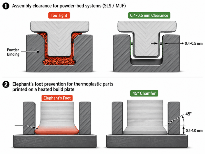
For powder-bed platforms like SLS and MJF, a sliding or interlocking clearance between 0.4mm and 0.5mm is mathematically mandatory. Because these machines sinter or fuse nylon powder inside a densely nested cake, tighter clearances trap radiant heat. This semi-sisters the raw powder inside the internal interlocking chambers, causing mechanical binding or permanent sticking that ruins the assembly’s movement.
Eliminating “Elephant’s Foot” Failures
When printing thermoplastic models directly on a heated build plate, the initial layers are subjected to constant downward compression and thermal radiant heat. This triggers a physical spreading defect known as “Elephant’s Foot,” which expands the baseline dimensions of the part and jams interlocking assemblies. To counteract this physical behavior, engineers should integrate a 45 ° base chamfer (ranging from 0.5mm to 1.0mm) along the bottom edges of the CAD model that meet the build platform, completely preserving functional tolerances.
Advanced Cost Optimization: Volumetric Shelling vs. Blind Infill Scaling
In hobbyist desktop printing, users routinely alter “infill percentages” via software sliders to change part weight or strength. In a commercial or industrial procurement ecosystem, relying on infill sliders is an incredibly inefficient approach that extends machine run-times, slows down thermal cooling, and wastes premium resins or powders. True industrial cost and weight optimization rely strictly on Topology Optimization and Volumetric Shelling.
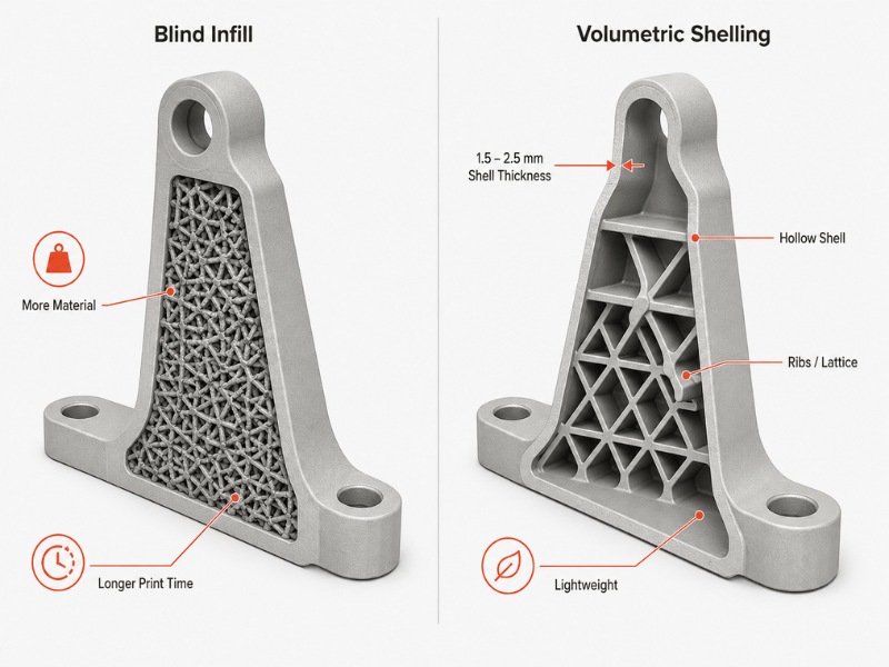
If a structural component requires immense rigidity but must remain lightweight, designers should model a completely hollow, cored-out section. The exterior shell thickness should be kept between 1.5mm and 2.5mm (depending on the engineering material) while integrating internal ribbed reinforcements or a mathematically defined lattice structure to distribute mechanical stresses uniformly.
The 3.0mm Drainage Mandate
For industrial powder-bed platforms (SLS/MJF), designing a hollow, shelled structure strictly mandates the inclusion of a minimum of two escape holes (drainage vents) that are at least 3.0mm in diameter.
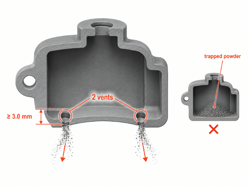
Without these dedicated extraction channels, the un-sintered nylon powder or liquid resin remains permanently trapped inside the core. During the post-processing phase, this trapped material bakes and cements into a heavy, solid mass. This entirely defeats the original purpose of volumetric weight reduction, compromises the balance of the part, and directly drives up your material expenses by charging you for wasted, trapped raw resin.
Factory-Direct Engineering: Secure Your Additive ROI
Sourcing functional prototypes and low-volume production runs through decentralized digital marketplaces introduces unpredictable execution risks into your hardware pipeline. These digital brokers operate merely as middleman storefronts, routing your confidential CAD data to an untraceable network of unvetted, sub-contracted job shops that frequently lack standardized machine calibrations and material certifications. As a result, components often arrive with poor interlayer adhesion, out-of-spec dimensions, and hidden structural defects.
RapidDirect completely eliminates these supply chain vulnerabilities by acting as a fully integrated, factory-direct 3d printing service. We own and operate a centralized, 20,000㎡ advanced manufacturing facility housing industrial SLS, MJF, SLA, and SLM production lines under one roof, guaranteeing absolute batch-to-batch repeatability and total material traceability. Driven by a proprietary, AI-powered automated DFM engine and an elite team of internal manufacturing engineers, our cloud platform instantly cross-references your CAD geometry against real-world thermoplastic crystallization boundaries and tool path nozzle integers to audit every layer before a single laser fires.
Leverage Factory-Direct Control with RapidDirect
Stop letting amateurish checklists risk your hardware timeline. Navigate to the RapidDirect online platform and upload your CAD files directly to our ecosystem. Gain instant access to our advanced industrial injection molding service and high-capacity 3d printing service networks. Within minutes, receive an automated, data-driven quotation paired with a comprehensive, free AI-driven DFM wall thickness and geometric verification report. Protect your intellectual property, eliminate broker markups, and accelerate your product design cycles with absolute factory control today.
FAQ for Enterprise Sourcing
To drastically minimize support structures and decrease post-processing labor costs, engineers must design around self-supporting angles. Ensure that steep features maintain an angle of less than 45 ° relative to the vertical print plane. For complex, large-scale enclosures, consider splitting the geometry into multiple divisible sections that can be printed flat on the build platform without support, and then permanently bond or mechanical-fit them together post-printing.
When exporting your finalized design from platforms like SolidWorks or Creo to an .STL, .OBJ, or .3MF file, setting the correct chordal tolerance is critical. If your resolution is set too low, the face geometry will display visible “faceting” (flat triangles on curved surfaces), ruining part aesthetics and tolerance fits. If the resolution is too high, the file size explodes, causing slice engine buffer lag and errors. For high-precision industrial prototyping, always export with a chordal deviation tolerance between 0.01mm and 0.05mm to guarantee flawless surface curves.
No. In solid and structural mechanics, the relationship between infill density and ultimate tensile strength is strictly non-linear. Doubling your internal infill density from 25% to 50% only alters the part’s moment of inertia along a flattening efficiency curve, while heavily increasing material cost and machine print time. To achieve superior structural rigidity at a lower price point, engineers should optimize the exterior wall shell thickness rather than blindly injecting raw material into the internal core.
Exceeding the maximum safe wall thickness limits causes intense thermal heat accumulation. In powder-bed fusion (SLS/MJF) or high-temperature industrial FDM, excessively thick solid sections trap heat inside the center of the part. Because the exterior skin cools faster than the insulated core, the resulting uneven thermal contraction creates intense internal tension, which leads to internal void formation, severe skin warpage, or catastrophic delamination post-production.