

Why Tray Frames Warp When Nothing Touches Them
The first thing a new engineer notices about a warped battery tray is that nothing in the process touched it. There is no punch, no clamp pressure, no cutting force — and yet an outline that was flat on the table comes off the machine bowed, or a long flange drifts half a tenth out of position. The instinct is to blame the fixtures. The cause is the heat.
A fibre laser is a thermal separation process: it melts the metal in a narrow kerf and an assist gas blows the molten material out. Everything that happens to the tolerance of the part follows from how that heat is delivered, how it dissipates through the section and how the gas behaves at the nozzle. Three interactions decide the result — absorption at the beam wavelength, the thermal balance across the blank, and the gas boundary layer — and they are the reason the same program can hold a tight band on a 1.5 mm panel and lose it entirely on a 4.0 mm one.
How a Fibre Laser Cuts Aluminium
Aluminium is a reflective metal, which is why the choice of laser source matters more than it does for steel. A fibre source delivers a beam at 1.06 µm, close enough to the absorption behaviour of aluminium to couple efficiently; a CO2 source at roughly 10 µm loses most of its energy to reflection. At the fibre wavelength a 1.5–4.0 mm aluminium sheet reaches melting temperature quickly, and the cut is made without any tool contact and therefore without tool wear.
Around the beam sits the gas. Nitrogen at 1.6–2.0 MPa travels coaxially through the nozzle, ejects the molten aluminium downward out of the kerf and shields the cut faces from oxygen, so they come out free of oxide scale. The standoff matters as much as the pressure: keep the nozzle within about 1.5 mm of the sheet, and size the bore to the gauge, or the gas jet loses its shape through the boundary layer and the kerf fills with dross and burrs.
The focus position is set slightly below the surface on this thickness range, which spreads the energy through the section and keeps full penetration, and the focus compensation is calibrated with the kerf compensation so that every edge moves to its programmed position rather than to the beam centre.
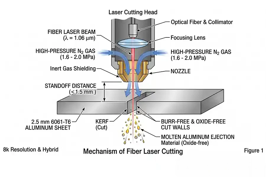
The mechanism: a 1.06 µm beam through the nozzle, nitrogen at 1.6–2.0 MPa ejecting the molten aluminium from the kerf, and a standoff under about 1.5 mm.
The Tolerance Bands a Cut Edge Can Hold
Thermal cutting tolerances are not one number. On a battery tray the drawing normally needs two: a general band for the outline, and a much tighter one where the pack has to seal or a module has to locate. In practice ±0.05 mm is the working band on perimeter blanks, long flanges and non-sealing edges, while bolt-hole centres and sealing faces are held to ±0.01 mm — and that second band is normally the result of secondary machining, not of the laser.
Where the drawing leaves dimensions unlabelled, general tolerances follow ISO 2768-1 (medium or fine depending on what the design calls for), and geometric callouts follow ASME Y14.5-2018. Thermal-cut edge classes are defined in ISO 9013:2017, which is the standard to name when an edge quality band, rather than a dimension, is the requirement.
Two machine-level effects set the floor on what the process can promise. Servo backlash — the lost motion when an axis reverses — feeds position error into long contours, and kerf compensation shifts every edge by half the kerf width in the direction the program chose. On a long flange the cumulative effect of both is what pushes the achievable deviation toward the ±0.05 mm end, whatever the callout says.
| Feature on the tray | Band | How it is produced |
|---|---|---|
| Perimeter blank, long flanges, non-sealing edges | ±0.05 mm | Fibre laser cut, kerf compensated |
| Bolt-hole centres, module locating faces | ±0.01 mm | Laser-cut undersize, then milled or reamed |
| Sealing faces and seal-groove walls | ±0.01 mm, with a flatness callout | Machined after cutting, then checked on a plate |
| Unlabelled dimensions | ISO 2768-1 medium or fine | Whichever class the drawing states |
| Edge quality where a class is called out | ISO 9013:2017 class | Power modulation, focus and gas settings |
This is the callout that causes the most rework in tray programs: a ±0.01 mm tolerance applied to the whole perimeter. Over a long flange, the achievable edge deviation drifts toward the ±0.05 mm band no matter how good the machine is, and the sensible separation is to keep the laser for the baseline geometry and reserve the tight band for the interfaces that actually need it.
Heat, HAZ and Distortion
The heat-affected zone is the band beside a cut where the alloy has been heated enough to change — but not melted — and in 6000-series aluminium that means the strengthening precipitates are dissolved. In 6061-T6, a solution-treated and artificially aged alloy, the material immediately beside the kerf is therefore locally weaker than the parent sheet, and it is the place where a crack or a distorted seal groove will start.
The depth of that band is controllable. Dynamic power modulation drops the duty cycle where the beam would otherwise dwell — corners, small radii, deceleration points — and holds HAZ depth at 0.08 mm or less. A constant-power pass on the same blank roughly doubles it, because the energy keeps arriving while the machine is slowing down. The same logic applies to piercing: segmented pulses leave pauses for heat to escape instead of parking the beam at one point until the material gives way.
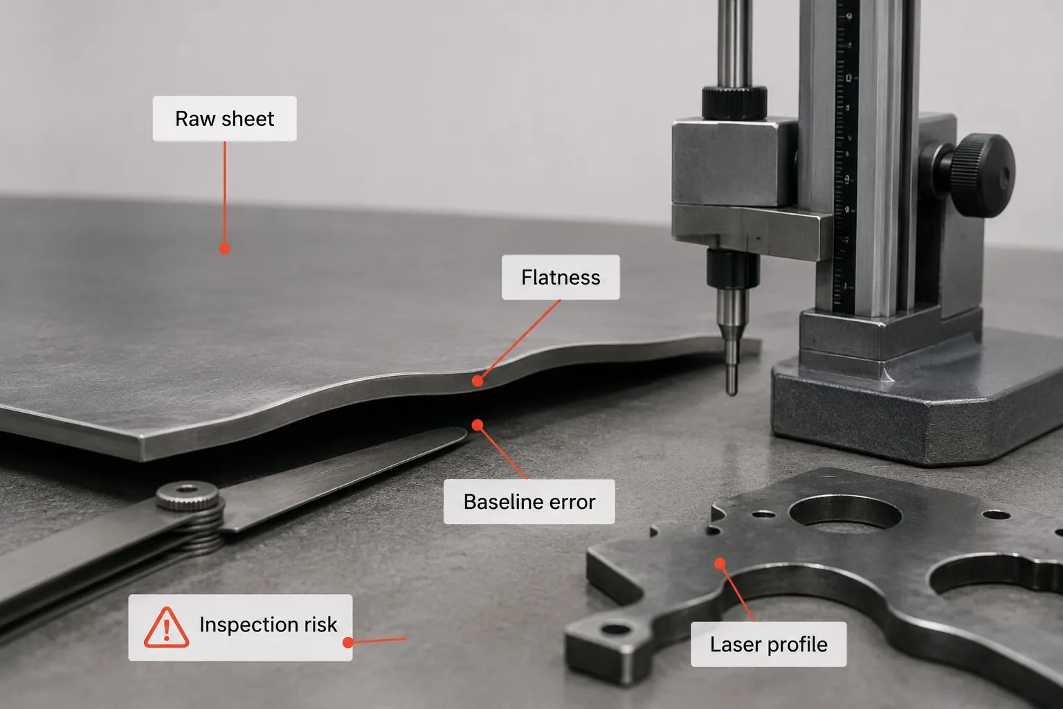
Thickness changes the balance. A 1.5 mm wall radiates heat into the surrounding material much faster than a 4.0 mm wall, so transverse expansion is uneven along the section and residual stress builds once cooling lags the beam. That is why HAZ depth — not cutting force, and not kerf width alone — is the number that predicts whether a large-span floor stays flat, and why a flatness callout on a tray floor should be checked after the part has cooled rather than as it comes off the bed.
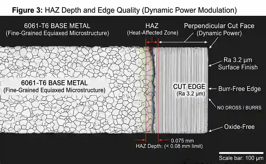
A 6061-T6 cut face under power modulation: heat-affected zone held at 0.075 mm against a 0.08 mm limit, with a burr-free, oxide-free edge at around Ra 3.2 µm.
Cut Strategy: Sequence, Micro-Joints, Fixturing
With power and gas set, the remaining control over distortion is geometric: the order in which the contours are cut and how the part is held while they are cut.
- Leapfrog cutting. Instead of walking around one contour and then moving to the next, the program jumps between distant regions so the heat is spread across the blank rather than concentrated along one edge. On a large tray floor this is the single most effective change.
- Micro-joints. Small uncut tabs, typically around 0.8 mm, anchor the part to the skeleton until the end of the program. They matter specifically because the assist gas is being driven into the kerf at up to 2.0 MPa: with most of the perimeter already cut, a partly-free part can shift under that flow, and the tabs remove the risk. They are broken or trimmed after the cut.
- Sequence inside the part. Internal features — cooling-channel openings, vent holes, cross-beam bores — are cut before the outer profile, so the outline that defines the part's position in the fixture is cut last.
- Support and clamping. Fixtureless cutting on a slat table is normal for trays, but the support spacing matters: an unsupported span under a heated blank sags, and the sag shows up as a flatness deviation rather than as a dimension. Where the flatness callout is tight, it is cheaper to add support than to add a machining step.
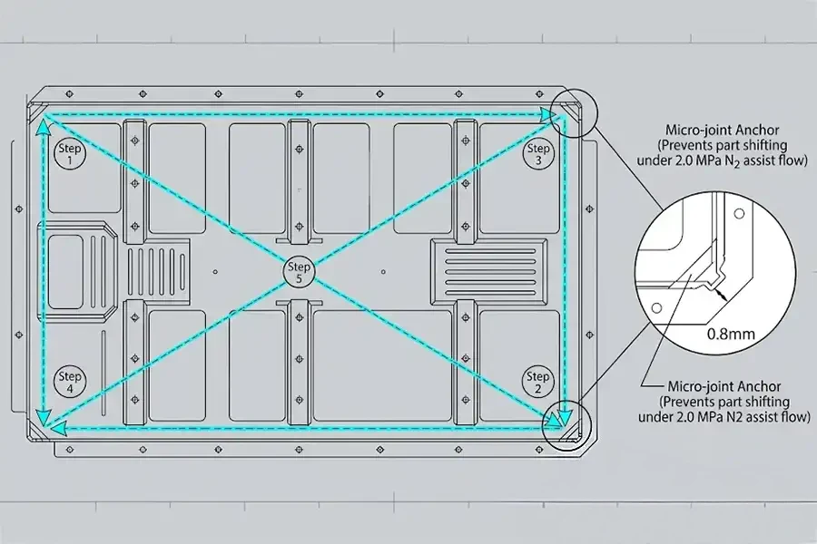
A leaning cut sequence: steps 1–5 jump between distant contours so heat does not build on one side, and 0.8 mm micro-joints hold the part against the 2.0 MPa assist flow until the program ends.
Edge Quality and What It Means for Welding
Nitrogen assist produces a cut face that is oxide-free and free of dross, with a surface finish in the region of Ra 3.2 µm on 6000-series sheet. That finish is the reason a laser-blanked edge can go straight into welding or adhesive bonding without a pickling or brushing step: there is no oxide layer to interfere with the weld pool and no rolled burr to hold contamination.
Two conditions have to hold for that to be true. The gas has to be doing its job — oxygen assist at the same pressure adds exothermic heat, darkens the edge and leaves the surface the welding process does not want — and the cut parameters have to be matched to the gauge, because under-cutting thick stock leaves roughness and dross while over-running thin stock burns the edge. Cut-edge colour is the practical indicator: a consistent bright edge means the gas/energy balance is right, and a dark or discoloured edge is telling you the heat input is too high before any measurement does.
Where a surface finish is specified rather than an edge condition, the surface roughness chart is the reference for how Ra values translate between processes, and how to cut sheet metal covers how the cutting route changes the edge it leaves.
Alloys, Gauges and Profiles That Suit the Process
The routine window for tray work is 1.5–4.0 mm in 6000-series sheet. Within it, the behaviour is predictable: 6061-T6 and 6082-T6 cut with straight, square edges and a consistent finish, and 5182-O cuts cleanly in the annealed temper at the cost of structural strength. Extruded profiles and tubes are cut on dedicated tube-laser setups rather than on a flat-bed machine.
Outside the window the arithmetic changes rather than the process improving. As thickness rises the focus quality and the gas ejection degrade, so the cut face roughens and the achievable tolerance opens up; cast plate and deep stepped pockets are milling work; and a foam-cored laminate cannot be pierced in a single pass in any case, because the trapped core gas expands faster than the plies transfer heat. Compare the two routes on the features the design actually needs:
| Attribute | Fibre laser cutting | Stamping or CNC milling |
|---|---|---|
| Suited gauge | 1.5–4.0 mm | Well beyond that ceiling; cast plate for thick sections |
| Typical stock | 6061-T6, 6082-T6, 5182-O sheet and extrusions | Cast plate, formed blanks |
| Edge finish | Ra around 3.2 µm, burr-free, oxide-free | Sheared or milled edge |
| Where it wins | Tray blanks, closures, cooling-channel openings, prototypes and low volume | Deep stepped grooves, thick sections, tight bores |
The process is chosen by gauge and geometry, not by alloy grade: the same 6082-T6 sheet is a laser part at 3 mm and a milling part as a thick stepped housing.
Inspecting a Cut Tray
Inspection follows the function of each feature rather than the drawing's order of dimensions.
- Sealing and locating features first. Bolt-hole centres, module locating faces and seal-groove walls against their ±0.01 mm requirement — these decide whether the pack seals, and they are the features most likely to have been produced by a second operation.
- Profile deviation on the outline against the ±0.05 mm band, measured over the long flanges where the thermal effects accumulate.
- Flatness after cooling, on a surface plate or with a scanner, not while the part is still warm on the bed.
- Kerf width against the compensation value in the program, together with the cut face checked for dross and oxide — both are early indicators that the nozzle, focus or gas pressure has drifted.
- A dimensional cadence through the run, short enough to catch nozzle and focus wear before it produces out-of-tolerance parts.
Records follow the parts: the first-off report, the material certificate for the sheet and the cut-parameter sheet for the program are what let a tray be traced back if a pack fails a leak test months later.
Laser Cutting Trays at SHBD Metal
Fibre laser cutting here covers 1.5–4.0 mm aluminium tray work alongside the stainless and steel that runs through the same shop: tray blanks, closures, cooling-channel openings and mounting plates, cut flat-bed, with tube-laser capacity for extruded sections and CNC machining for the sealing and locating features that need a tighter band than the laser gives.
Cut parameters are documented per program rather than left to the operator: assist gas pressure and standoff are specified with the gauge, kerf compensation is recorded with the program, and the first-off parts are inspected against the same bands the drawing calls out. Where an edge needs a class rather than a dimension, it is specified to ISO 9013:2017 so the requirement is measurable on both sides.
On the quality system, plainly: we work to ISO 9001:2015, in place here since 1994, with 150+ people, 100+ machines and 7 dedicated inspectors. If a programme is written around IATF 16949 or ISO 13485, say so at the RFQ stage and we will tell you whether the route fits instead of implying a certificate we do not hold.
Send the drawing with the alloy, the gauge and the features that have to seal, and we will come back with the cut strategy, the tolerance split between laser and machining, and the support arrangement the flatness callout needs — see laser cutting, CNC machining and quality control. Related reading: laser cutting tolerances and how the process works.
FAQs
How is fibre laser cutting different from punching a tray?
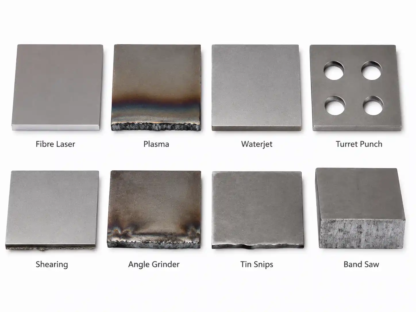
Punching separates the sheet by shear between a punch and a die, so the material sees a mechanical load and the edge is a fracture surface. Laser cutting melts and ejects the material with a focused beam: no contact, no tool wear, and the geometry can change between parts without a die. The trade-off is thermal. A punched or sheared edge has no heat-affected zone, a laser-cut edge always does, and the whole tolerance question for trays comes down to how that heat is managed. Thermal-cut edge classes are defined in ISO 9013:2017, which is the standard to quote when an edge profile is called out.
Why nitrogen rather than oxygen for aluminium battery enclosures?
Because nitrogen is inert and oxygen is not. Oxygen assist adds exothermic energy to the cut, which raises the heat input and leaves a dark oxide on the edge — exactly what a weld-ready, weld-quality surface does not want. Nitrogen at 1.6–2.0 MPa blows the molten metal out of the kerf and shields it, so the cut face comes out oxide-free. Pressure is a trade: more pressure ejects material more cleanly on thicker stock and widens the kerf slightly, which is why 1.6 MPa is typically used on the thin end of the window and 2.0 MPa on the thick end.
The laser never touches the part, so why does a tray warp?
Because the distortion is thermal, not mechanical. Cutting one long contour heats one side of a large blank, and the surrounding cold material restrains the expansion, so the blank bows and holds residual stress once it cools. Three things decide how much: how the heat dissipates through the section (a 1.5 mm wall radiates it much faster than a 4.0 mm one, so the expansion is unbalanced), how the energy is delivered at corners and deceleration points, and how the assist gas behaves in the boundary layer. Cut order and cut strategy move the number more than travel speed does.
What tolerance can a cut tray edge actually hold?
Two bands, chosen by feature rather than by the part: ±0.05 mm on perimeter blanks, long flanges and non-sealing edges, and ±0.01 mm on bolt-hole centres and sealing faces, which is normally a secondary machining operation rather than a laser one. Unlabelled dimensions fall back to ISO 2768-1 medium or fine, and geometric callouts follow ASME Y14.5-2018. Over a long flange, cumulative thermal expansion pushes the achievable edge deviation toward the ±0.05 mm end regardless of what the drawing asks for, which is why the same ±0.01 mm band across an entire tray perimeter is the most common unachievable callout in this work.
How is the heat-affected zone kept small?
By modulating power rather than running a constant pass. Dynamic power modulation drops the duty cycle at corners and deceleration points, where the beam dwells and heat accumulates, and holds the HAZ depth at 0.08 mm or less; a constant-power pass on the same blank pushes it to roughly double that. The metallurgical reason to care: in a 6061-T6 tray the strengthening precipitates are lost in that band, so it is locally weaker and is where a crack or a distorted seal groove will start. Piercing is managed the same way, with segmented pulses that leave pauses for heat to escape instead of parking the beam at one point.
What are micro-joints and leapfrog cutting for?
Both solve the same problem — keeping a nearly-free part from moving while it is being cut. Leapfrog cutting jumps between distant contours instead of walking around one edge, so heat never builds up in one region. Micro-joints are small uncut tabs (around 0.8 mm) that hold the part to the skeleton until the end of the program, which matters when nitrogen is being pushed at 2.0 MPa into a kerf and the part no longer has enough material left to stay put on its own. They are then broken or trimmed off.
Which alloys and gauges suit laser cutting, and where does it stop?
The routine window is 1.5–4.0 mm in 6000-series sheet: 6061-T6 and 6082-T6 cut with straight, square, burr-free edges, and 5182-O cuts cleanly but gives up strength as an annealed temper. Extruded sections are cut on tube-laser setups. Beyond that window the process changes: cast plate and deep stepped pockets belong to milling, the focus quality and gas ejection fall away as thickness rises, and a laminate with a foam core cannot be cut in a single pass because the trapped core gas expands faster than the plies take heat. The limit is set by gauge, not by alloy grade.
What should be inspected on a cut tray?
The features that carry the seal and the module, in that order: bolt-hole centres and sealing faces against their ±0.01 mm requirement, profile deviation on the outline against the ±0.05 mm band, flatness on a surface plate after the part has cooled, kerf width against the compensation value in the program, and the cut face for dross and oxide. First-off inspection is the real gate; a dimensional cadence through the run catches focus and nozzle wear before they show up as out-of-tolerance parts.
Summary
Distortion in a laser-cut battery tray is a thermal problem with mechanical consequences. Nitrogen assist at 1.6–2.0 MPa keeps the cut face oxide-free and weld-ready, a standoff under about 1.5 mm keeps the gas jet in shape, kerf and focus compensation put the edge where the program says it should be, and dynamic power modulation holds the heat-affected zone at 0.08 mm or less so the alloy beside the cut keeps its strength. Beyond that, cut order does the rest: leapfrog sequencing spreads the heat and micro-joint anchors keep a nearly-free part from moving under the gas flow.
The tolerance split is what makes a tray programme work: laser-cut to ±0.05 mm on the outline, machined to ±0.01 mm where the pack seals and the modules locate, with ISO 9013:2017 named when an edge class is the requirement. Send the drawing and the sealing requirements, and we will say which features belong on the laser and which need a second operation — request a quote.
Watch: Laser Cutting on the Floor
Clips from the shop floor go up on our TikTok, including the fibre laser running thin-gauge sheet and finished tray components:
Watch it on TikTok: @shanghaibouchard — laser cutting
Comment
0 comments
Got thoughts or experiences to share? We’d love to hear from you!